background image

A:

 9300 S.W. Gemini Drive Beaverton, OR 97008 USA

W:

 www.biamp.com

DEC

 202

2

Note:

 Every effort has been made to ensure that the information contained in this manual was 

complete and accurate at the time of printing. However, due to ongoing technical advances, 

changes or modifications may have occurred that are not covered in this manual. The latest 

version is available at 

www.biamp.com

CONTACT US

Email


[email protected]

Web

support.biamp.com

Safety and Compliance

www.biamp.com/compliance

Warranty

www.biamp.com/legal/warranty-information

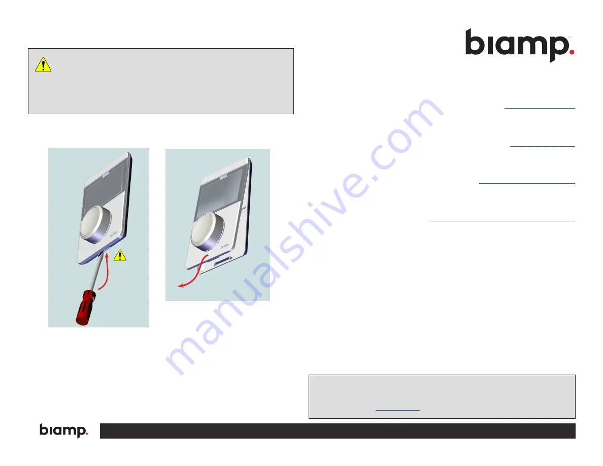
Important:

 Do not snap the face plate onto the back plate until all finish 

work is done to the wall surfaces and the Ethernet cables have been 

connected. The face plate can be removed by inserting a flat screwdriver into the 

slot at the bottom of the back plate, carefully depressing the tab and pulling the 

face plate out and down. The tab is stiff and care should be taken to not damage 

the plastic. 

MAINTENANCE

Figure 11.

 Remove Face Plate

Summary of Contents for TEC-X 1000

Page 1: ...information supplied by this manual relates to physical connections and device setup For more details on software setup including programming the functions of the rotary knob please consult the Tesira Help File The TEC X 1000 Wall Control Panel is designed to be mounted directly to a 4 X 2 electrical junction box per room design requirements each remote requires its own box An optional tabletop mo...

Page 2: ...ows easier separation of the face and back plates to prevent damage 1 See Figure 2 Pull down and out on the face plate to separate it from the back plate and remove the pull tab NOTE Do not snap the face plate onto the back plate until all finish work is done to the wall surface and the Ethernet cables have been connected TEC X 1000 Wall Control Panel 1 Capacitive Touch LCD Display 2 Rotary Knob 3...

Page 3: ...e gang box 5 See Figure 5 Insert the Ethernet cables into the appropriate ports on the face panel Figure 3 Insert Ethernet Cables Figure 5 Connect Ethernet Cables INSTALLATION CONTINUED 2 See Figure 3 Insert the control Ethernet cable through the port labeled IN 3 See Insert the downstream Ethernet cable through the port labeled OUT as required ...

Page 4: ...r the installed back plate a See Figure 6 Align the upper clips into the two receptacles at the top of the back plate b Snap the lower clip into the receptacle on the back plate 7 Up to four TEC X 1000 or 2000 devices may be daisy chained together in any combination four devices total The maximum distance allowed between devices in a daisy chain is 100 meters maximum of 400 meters overall Figure 6...

Page 5: ...ll be available NOTE Tesira programmers have the option of locking the device so that a PIN code will be required to access functions 3 The buttons and rotary knob may be configured in the Tesira software The interface may be customized to match the physical device 4 The Tesira software allows for multiple pages each with unique icons text button color etc Figures 8 and 9 show examples of color an...

Page 6: ...ACT US Email support biamp com Web support biamp com Safety and Compliance www biamp com compliance Warranty www biamp com legal warranty information Important Do not snap the face plate onto the back plate until all finish work is done to the wall surfaces and the Ethernet cables have been connected The face plate can be removed by inserting a flat screwdriver into the slot at the bottom of the b...

Reviews: