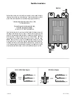
Back-Box Installation
Remove the back-box from the front panel (controls). Route cables through a
‘knock-out’ hole on the rear of the back-box. Install the back-box in a wall or
panel, in the same orientation as any standard single-gang electrical box.
The mounting surface may be from 1/8” to 1” thick.
(3.175mm to 25.4mm)
The mounting cavity must be exactly 3.6” high,
2.25” wide, and at least 2.75” deep.
(91.44mm H x 57.15mm W x 69.85mm D)
Insert the back-box into the wall or panel, then tighten the flange screws until
the flanges hold the box securely in place. Wire the remote panel pre-wired
pigtails to the appropriate cable conductors. Soldered connections with heat-
shrink insulation, or properly sized wire nuts, are recommended. Mount the
front panel to the back-box, being careful not to pinch or short the wires.
NOTE:
When an RP-S4 is used with an
RIK
Remote Interface Kit, the RIK
circuit board will not fit inside the standard single-gang electrical back-box.
Therefore, the RIK must be installed external to the back-box (
yet close enough
to be connected using the wire harnesses provided
). An alternative is to utilize
a double-wide electrical back-box, which has the additional space for an RIK.
Back-Box
flange
flange
knock-outs
RP-L1 & RP-L2 Block Diagram
25k
Ω
linear
GND C +10V
green
red
white
low (ccw)
wiper
high (cw)
cw
ccw
w
RP-S4 Block Diagram
DPDT
green
red
white
down (depressed)
wiper
up (released)
up
wiper
down
white
red
green
585.9131.90A
19Mar07
Summary of Contents for RP-S4
Page 5: ......


