background image

UNITE – System information

12

7.        Create/define a new pairing

Transmitter and receiver must be paired to enable them
to communicate with one  another. The code required
for this is generated in the charger and transmitted
 during the pairing process to both transmitter and
 receiver.

Note:

For group ID 256 only, a factory preset code is

used that cannot be changed. You can use this group
ID for a system without pairing. 

To establish a pairing with a charging unit, please
 proceed as described below:

1.     On the transmitter, set the group ID you wish to use

for pairing.

2.  Insert 

one transmitter only

in the charger. If more

than one transmitter is used in the charger, pairing
will not start and the charger’s status indicator 

will show an error  message (see table 2).
 Alternatively you can connect the transmitter using
a USB cable connected to the charger’s USB port.

3.

Insert one or more receivers to be paired with the
transmitter into the charger’s  charging compart-
ment. You can also connect another receiver to the
charger using the USB port. Remove all receivers
that are 

not

to be paired. Should no receiver be

connected to the charger, pairing information is
 stored in the charger only. This is used for later
 pairing without connecting the transmitter to the
charger.

4.  To transmit information from the transmitter to the

receivers in the charging compartments and to the
charger itself for future pairings, hold down the
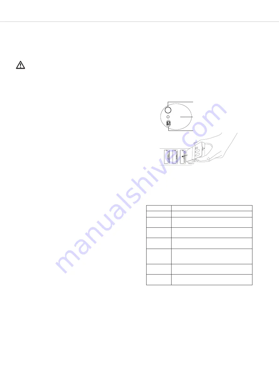
“Pair/Reset” button 

on the charger for more than 

2 seconds. The “Status” light 

will flash yellow for a

few seconds if the pairing is successful. The status
light will then remain yellow  because the pairing
 information is now also saved in the charger.

5.  If you wish to pair other receivers, remove the trans-

mitter and all receivers from the charger, switch to
“Pair & Charge” 

and insert the unpaired receivers

into the  charger. The pairing information will be
saved immediately in the unpaired receivers. The
status light on the receiver will rapidly flash yellow
while this happens.

6.  If you have no further devices to pair, switch the

charger to “Charge only” 

.

7.  Switch on the transmitter and one receiver to check

that they have both been paired successfully. After
a few seconds the status light on the receiver will
light up green and show the channel name of the
transmitter.

8.  To delete pairing information stored in the charger,

hold the “Copy/Reset” button down for more than 
5 seconds. The status light 

will then remain

 permanently green.

Display 

Status

Off 

The device is switched off

Green 

• Device is ready to use
• No pairing information saved

Flashing
yellow

Pairing information is being copied to the
charger or receiver

Yellow 

Pairing information has been stored in
the charger

Flashing
green/
yellow

Device is being localised

Flashes red
5 times

• No transmitter
• Too many transmitters

Flashing
red rapidly

• Operating error
• Charging error

In pairing mode (switch to “Pair & Charge”), the status
light 

on the charger will display the following infor-

mation: 

Pair/Reset

Status

• Pair & Charge
• Charge only

Pairing with Unite charger

Table 2

Found on charger

Summary of Contents for Unite CC-24P

Page 1: ...UNITE DIGITALWIRELESS COMMUNICATION SYSTEM OPERATING INSTRUCTIONS ...

Page 2: ...oop 17 9 1 5 How to connect a microphone 17 9 1 6 How to connect an external audio source 18 9 1 7 Switching on or off 18 9 1 8 Set the channel name 19 9 1 9 Adjust the volume 19 9 1 10 Mute function 19 9 2 Unite RP RP T bodypack receiver 20 9 2 1 Supplied accessories 20 9 2 2 Operating controls 20 9 2 3 How to wear the bodypack receiver 21 9 2 4 How to connect a headphone headset induction loop 2...

Page 3: ...UNITE Contents 3 14 Overview Unite components 33 15 Technical specifications 34 ...

Page 4: ...icing is required when the apparatus has been damaged in any way such as power supply cord or plug is damaged liquid has been spilled or objects have fallen into the apparatus the apparatus has been exposed to rain or moisture does not operate normally or has been dropped Location The equipment must be set up so that the mains switch mains plug and all connections on the rear of the device are eas...

Page 5: ...eratures particularly in association with a high charging status result in irreversible damage of the battery pack If you are not intending to use the battery for an extended period or are planning to put it into storage it is advisable to lower the battery s charging level to around 50 and to store it at temperatures of maxi mum 30 C In order to ensure safe transport by land sea and air the batte...

Page 6: ...icence L exploitation est autorisée aux deux conditions suivantes 1 l appareil ne doit pas produire de brouillage et 2 l utilisateur de l appareil doit accepter tout brouil lage radioélectrique subi même si le brouillage est susceptible d en compromettre le fonctionnement This equipment has been tested and found to comply with the limits for a Class A digital device pursuant to Part 15 of the FCC ...

Page 7: ...er has found a suitable frequency the status indicator lights green to indicate that the transmitter is ready for operation The factory set name Unite is displayed 6 Switch on the receiver s by briefly pressing the button status indicator Unite 7 The status indicator on the receiver initially lights red Once the receiver is connected to the transmitter the status indicator lights green The Connect...

Page 8: ...groups through several walls simultaneously The walls are made of reinforced concrete and all ceilings are metal clad 6 3 Automatic frequency and group management A further benefit of this technology is automatic frequency management This means you need not worry about frequencies as the system itself controls transmission and adjusts automatically for secure transmission It recognises the availab...

Page 9: ...ite TH transmitter to select Group ID from the sub menu Select the menu button on the Unite TP or Unite TH transmitter to configure group ID Use the multifunction button on the Unite TP or Unite TH transmitter to select the desired group ID Press the menu button on the Unite TP or Unite TH transmitter to confirm the selected group ID Important Make sure that you select the same group ID for all de...

Page 10: ... the Channel Name submenu Briefly press the menu button to enter the channel name Use the multifunction button to scroll through the characters When the requested character appears confirm using the menu button You can enter five characters at maximum As soon as you select the configured transmitter on the receiver the set name will be displayed on the receiver s display The diagram Channel Name s...

Page 11: ...ate between showing the relevant channel name and the KEY error message Encryption of the audio signal is explained schematically in the Encryption diagram Note For group ID 256 only a factory preset code is used that cannot be changed You can use this group ID for a system without pairing Important The transmitter and receiver can only communicate if the settings for group ID channel name and enc...

Page 12: ...t button on the charger for more than 2 seconds The Status light will flash yellow for a few seconds if the pairing is successful The status light will then remain yellow because the pairing information is now also saved in the charger 5 If you wish to pair other receivers remove the trans mitter and all receivers from the charger switch to Pair Charge and insert the unpaired receivers into the ch...

Page 13: ...r adapter to the USB port on the transmitter receiver Connect the plug of the USB power adapter to a power outlet The charging process will start automatically It is not possible to use the transmitter receiver during charging The battery s charge status is shown on the LED indi cator of the relevant transmitter receiver See the following table Charging with Unite charger Charging with USB power a...

Page 14: ...Pair Charge or Charge only Charging modules with 4 charging compartments each Slots for more optional charging modules or one optional charging module and one optional compartment for storing the Unite TH handheld transmitter Pair Reset Status Pair Charge Charge only Pair Reset Status Pair Charge Charge only Rear view Reset button Ethernet connection USB connection Mains connection Fuse drawer 2 x...

Page 15: ...g the Unite Cockpit Case will automatically update the firmware of the Unite transmitters receivers during the first charging process Just insert the transmitters receivers into the charging compartments During the firmware update the status indicator light of the Unite transmitters receivers will illuminate red This process will take approx 5 minutes Should the process take longer than 10 minutes...

Page 16: ...guide Neck strap Two spare caps for the mute button 9 1 2 Operating elements Display On off and menu button Status indicator light Multifunction button Volume button Mute button Neck strap attachment Integrated microphone Headphone headset induction loop connection Microphone connector Line In 3 pin jack connector 3 5 mm USB port type C Belt clip Charging contacts Type plate ...

Page 17: ... connector to the microphone connector For pin assignment please refer to the Technical specifications The integrated microphone will be activated if the internal mode has been selected as an audio source in the menu or if the auto mode has been selected when there is no external microphone connected Note The integrated microphone was specially developed for the talkback function in conjunction wi...

Page 18: ...the transmitter is ready for operation The individual symbols mean Display of all active speakers Master 1st slave 2nd slave Highlighted display of current type of speaker Master 1st slave or 2nd slave Current channel name Bluetooth status various symbols depending on the status Headset connected Microphone muted Display of remaining battery capacity Display of the actual speaker Status indicator ...

Page 19: ...name will be displayed on the receiver s display 9 1 9 Adjust the volume Use the volume button to adjust the volume of a connected headphone headset or induction loop Press to increase the volume Press to reduce the volume Important Please note the safety instructions regarding too high volume 9 1 10 Mute function Use the mute button to mute the internal or externally connected microphone If the P...

Page 20: ...spare caps for the talkback button 9 2 2 Operating controls Display On off and menu button Status indicator light Multifunction button Volume button Talkback button only with RP T Neck strap attachment Integrated microphone only with RP T RP Connection for headphone and induction loop RP T Connection for headphone headset and induction loop USB port type C Belt clip Charging contacts Type plate ...

Page 21: ...ch as a trouser or skirt waist band 9 2 4 How to connect a headphone headset induction loop Unite RP You can connect headphones to the mini jack socket For those who are hearing impaired you can connect an induction loop e g IL 200 von beyerdynamic to the mini jack socket instead of headphones Unite RP T Connect headphones or a headset to the mini jack socket For those who are hearing impaired you...

Page 22: ...speakers Master 1st slave 2nd slave Highlighted display of current type of speaker Master 1st slave or 2nd slave Current channel name RP T only Headset connected Talkback function activated Display of remaining battery capacity Status indicator light during operation Indicator light Operating status Off Device is switched off Flashing yellow slowly Ready to operate and battery status 10 Out of ran...

Page 23: ...tegrated microphone when no headset is con nected Refer to the separate chapter on Menu items If the Toggle setting is selected in the Talkback menu press the button to activate the microphone of a connected headset or the integrated microphone if no headset is connected When you press the button a second time the microphone is deactivated Refer to the separate chapter on Menu items Please keep a ...

Page 24: ...ctive menu Depending on the device up to 4 main menus with submenus are available Audio Talkback Bluetooth only System The dashes at the bottom of the display in the individual menus show how many submenus or setting options are available in the respective menu If no setting is made or changed or if the button is not pressed the display returns to the main screen after a few seconds An active func...

Page 25: ...ne signal is selected in this menu Quality HD SD HD high quality 22 3 ms latency 50 14 000 Hz frequency range SD low quality 18 3 ms latency 200 7 000 Hz frequency range Mute Button Push Toggle The mute button can be used in two different ways Push means the device s own microphone signal is muted for as long as the button is held down Toggle means the microphone is muted when pressed once and rea...

Page 26: ...er effect in the category of dynamic processors and suppresses low signal transmission Input Effects Noise Gate Threshold 13 steps 48 dB to 12 dB In the Threshold menu you can set the threshold value above which the background noise is muted The lower the background noise the lower the threshold value should be set Input Effects Noise Canceller Off Low Mid High Noise cancellation ANC is a smart ad...

Page 27: ...nly the Master device can hear audio signals from the Sub Master Master Sub Master only the Master and all other Sub Masters can hear audio signals from all Sub Master devices in a group All All devices in a specific group are able to listen in on the signals of Sub Master devices RP T TP TP Device Menu path Level 2 Menu path Level 3 Adjustable parameters Description State Off Headset Phone PC The...

Page 28: ...this menu you can select the time from which the selected dimming level value is applied to the brightness of the display Radio Power Std Mid Low In this menu the transmission power of the transmitter is defined from standard to low You can use this setting to reduce the range to body pack receivers if you want to operate several transmitters in adjacent rooms simultanteously Device Mode Master Su...

Page 29: ... option of connecting external audio sources to the TP configured as Sub Master The external audio signals are then routed broadcast via the Master to the group Caution Changing configuration between Master and Slave takes a few minutes This involves restarting the device In order to make use of this function all devices must be within range 11 2 Talkback function The orange Talkback button on the...

Page 30: ...ter device two talkback channels can be activated simultaneously Unite offers the option to set up whether there should be one or two talkback channels Menu Talkback NOM Talkback When a Sub Master is active in the group the number of additional talkback channels that can be activated is reduced to one fig Guided tours with two guides Guided tours with two guides Function probably available from V1...

Page 31: ... due to various influencing factors it can also take several seconds Example A high number of wireless connections in the immediate vicinity and or too great a distance between transmitter and receiver 11 5 External interfaces analogue line in USB interface Bluetooth Devices of the type TP also offer interfaces with which audio signals can be received and or played The analogue line in is a 3 5mm ...

Page 32: ...ngs The volume can still be increased or decreased by pressing the volume button Example Press and hold the upper volume button and the lower function button RP RP T channel button or the lower volume button and upper function button RP RP T channel button for more than 3 seconds Press buttons crosswise 12 2 Automatic headset recognition Unite has automatic headset recognition at the 3 5 mm jack s...

Page 33: ... 710 709 NA 739 294 JP 739 340 Unite RP Digital bodypack receiver incl belt clip EU 710 679 NA 739 251 JP 739 316 Unite RP T Digital bodypack receiver with talkback function incl belt clip EU 710 687 NA 739 278 JP 739 324 Unite CC 24P Charging and transport case with a maximum of 24 charging compartments for Unite bodypack transmitters and receivers network connection integrated power supply 713 0...

Page 34: ... to 35 C Operation 10 to 40 C Storage 20 to 50 C Relative humidity 0 to 90 Unite TP DECT RF frequency range 1880 1930 MHz depending on the country DECT transmission power up to 250 mW peak depending on the country DECT operating range up to 300 m outside line of sight the actual operating range depends upon the RF output settings the surroundings the signal absorption signal reflection and signal ...

Page 35: ...4 charging compartments 225 W with 36 charging compartments Max charging time 4 hours Connections Ethernet USB type C Temperature range Operation 0 to 28 C Storage 20 to 50 C Relative humidity 0 to 90 Dimensions incl handle base L x W x H 530 x 445 x 178 mm 20 7 x 17 5 x 7 0 Weight Unite CC 24P 12 3 kg Unite CC 36P 12 7 kg Charging compartments Unite CC 24P max 24 for bodypack transmitters bodypac...

Page 36: ...r further distributors worldwide please go to www beyerdynamic com Non contractual illustrations Subject to change without notice Weitere Vertriebspartner weltweit finden Sie im Internet unter www beyerdynamic com Abbildungen nicht vertragsbindend Änderungen vorbehalten EN 3 BA UNITE 03 19 ...

Reviews: