4
5
3
1
2
180º
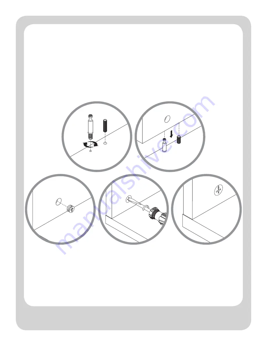
HOW TO USE THE CAM LOCK SYSTEM
Page 1: ...Service 1 877 436 7290 customersupport tenspringstreet com THIS INSTRUCTION BOOKLET CONTAINS IMPORTANT SAFETY INFORMATION PLEASE READ AND KEEP FOR FUTURE REFERENCE gray ivory Manufactured By BDDMI 13...
Page 2: ...NT R AIL REAR R AIL BACK PANEL FIXED SHELF X3 BOT TOM FR ONT PANEL A B C D E F G H I J K Before you begin 1 Check for damaged or missing parts 2 Use the carton as a working surface to prevent product...
Page 3: ...T CAUTION 1 Make sure the screws go through the pre drilled holes properly 2 Do not over tighten bolts 5 B olt x3 3 Cam x30 1 Wood D owel x32 2 Cam B olt x30 6 Lock Washer x3 4 15mm Pan Head S crew x1...
Page 4: ...Make sure the screws go through the pre drilled holes properly 2 Do not over tighten bolts 8 Allen Wrench x1 9 Wall Anchor x1 11 19mm Pan Head S crew x1 12 Wall Strap x1 10 Wall S crew x1 13 20mm Wood...
Page 5: ...5 3 1 2 4 5 180 HOW TO USE THE CAM LOCK SYSTEM...
Page 6: ...s into place Leave 1 2 of the dowels sticking out 2 Screw In cam bolts must be screwed down flush 3 Refer to page 5 for instructions on how to use the cam lock system 1 Wood D owel 2 Cam B olt 3 Cam N...
Page 7: ...ls into place Leave 1 2 of the dowels sticking out 2 Screw In cam bolts must be screwed down flush 3 Refer to page 5 for instructions on how to use the cam lock system NOT TO SCALE REFER TO PAGE 3 FOR...
Page 8: ...ACTUAL SIZE HARDWARE 1 Wood D owel 2 Cam B olt 3 Cam 1 Carefully tap small wooden dowels into place Leave 1 2 of the dowels sticking out 2 Screw In cam bolts must be screwed down flush 3 Refer to page...
Page 9: ...into place Leave 1 2 of the dowels sticking out 2 Make sure the bolts go through the pre drilled holes properly 3 Do not over tighten bolts NOT TO SCALE REFER TO PAGE 3 FOR ACTUAL SIZE HARDWARE 5 B ol...
Page 10: ...CTUAL SIZE HARDWARE 1 Wood D owel 2 Cam B olt 3 Cam 1 Carefully tap small wooden dowels into place Leave 1 2 of the dowels sticking out 2 Screw In cam bolts must be screwed down flush 3 Refer to page...
Page 11: ...LE REFER TO PAGE 3 FOR ACTUAL SIZE HARDWARE Begin by installing all of the screws along one edge of the back panel Next using a square or tape measure make sure that the case is square if using a tape...
Page 12: ...ead S crew 10 Wall S crew 12 Wall Strap 7 Washer 9 Wall Anchor position against wall mark position of strap hole on wall drill 1 4 hole tap in wall anchor fasten anti tip strap with wall screw provide...
Page 13: ...13 x10 STEP 8 1 Place cam covers over visible holes 14 Cam Cover NOT TO SCALE REFER TO PAGE 3 FOR ACTUAL SIZE HARDWARE...
Page 14: ...re Care Instructions Dust with clean lint free cloth Use furniture spray polish as needed Customer Service 877 436 7290 customersupport tenspringstreet com Your complete satisfaction is our number 1 p...
Page 15: ...877 436 7290 customersupport tenspringstreet com ESTE MANUAL DE INSTRUCCIONES CONTIENE INFORMACI N IMPORTANTE DE SEGURIDAD POR FAVOR LEA Y GUARDE PARA REFERENCIA FUTURA gris marfil Fabricado Por BDDM...
Page 16: ...nte el montaje Martillo Destornillador de Cabeza Plana Destornillador Phillips HERRAMIENTAS NECESARIAS LISTA DE PARTES PANEL SUPERIOR ENSAMBLE DEL LADO IZQUIERDO ENSAMBLE DEL LADO DERECHO PANEL INFERI...
Page 17: ...e los tornillos pasen por los agujeros pretaladrados de manera apropiada 2 No sobreapriete los tornillos 5 Per no x3 3 Leva x30 1 C lavija de M adera x32 2 Tor nillo de Leva x30 6 Arandela Fijadora x3...
Page 18: ...sen por los agujeros pretaladrados de manera apropiada 2 No sobreapriete los tornillos 8 Llava Allen x1 9 Taquete de Pared x1 11 19mm Tor nillo Largo de Cabeza de Nor ia x1 12 Cincha de Pared x1 10 To...
Page 19: ...5 3 1 2 4 5 180 COMO USAR EL SISTEMA FIJADOR DE LEVA...
Page 20: ...iente de 1 27 cm en las clavijas 2 Los tornillos de leva deben de estar atornillados al ras 3 Refi rase a la p gina 5 para instrucciones para como usar el sistema de levas 1 Clavija de M adera 2 Tor n...
Page 21: ...aliente de 1 27 cm en las clavijas 2 Los tornillos de leva deben de estar atornillados al ras 3 Refi rase a la p gina 5 para instrucciones para como usar el sistema de levas NO EST A ESCALA CONSULTE L...
Page 22: ...1 Clavija de M adera 2 Tor nillo de Leva 3 Leva 1 Con cuidado golpee las clavijas de madera en su lugar Deje un saliente de 1 27 cm en las clavijas 2 Los tornillos de leva deben de estar atornillados...
Page 23: ...ente de 1 27 cm en las clavijas 2 Cerci rese que los pernos pasen por los agujeros pretaladrados de manera apropiada 3 No sobreapriete los pernos NO EST A ESCALA CONSULTE LA P GINA 3 FOR HARDWARE DE T...
Page 24: ...Clavija de M adera 2 Tor nillo de Leva 3 Leva 1 Con cuidado golpee las clavijas de madera en su lugar Deje un saliente de 1 27 cm en las clavijas 2 Los tornillos de leva deben de estar atornillados a...
Page 25: ...ALA CONSULTE LA P GINA 3 FOR HARDWARE DE TAMA O REAL Empiece instalando todos los tornillos a lo largo de la orilla del panel posterior Despu s utilzando un cuadro o una cinta m trica aseg rese de que...
Page 26: ...10 Tor nillo de Pared 9 Taquete de Pared coloque contra la pared marque la posici n del agujero de la cincha en la pared taladre un agujero de 6 35 mm 1 4 golpee el taquete de pared apriete la cincha...
Page 27: ...13 x10 PASO 8 14 Cubier ta del Tor nillo 1 Ponga las cubiertas de los tornillos sobre los tornillos visibles NO EST A ESCALA CONSULTE LA P GINA 3 FOR HARDWARE DE TAMA O REAL...
Page 28: ...nstrucciones de cuidado Desempolve con un pa o limpio y libre de pelusa Utilice un pulidor en spray para muebles seg n se necesite Servicio al Cliente 877 436 7290 customersupport tenspringstreet com...