background image

www.betamaxhoist.com
1-800-233-5112


Summary of Contents for Beta Lite

Page 1: ...www betamaxhoist com 1 800 233 5112...

Page 2: ...B e t a M a x P o r t a b l e H o i s t s O p e r a t i n g a n d M a i n t e n a n c e P r o c e d u r e s M a n u a l www betamaxhoist com 1 800 233 5112...

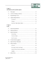
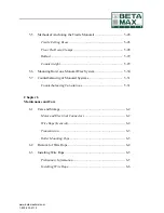
Page 3: ...ltage 1 6 Electrical Cables Strain Reliefs 1 7 Chapter 2 Safety 2 1 Safety Responsibilities 2 2 2 2 Safety Instructions 2 3 2 3 Safety Precautions 2 4 Pinch Points 2 5 Electrical Shock 2 5 Eye Protect...

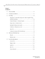
Page 4: ...formation Required for Safely Using Wire Rope and Wire Rope Slings 3 4 Nominal Strength or Catalog Strength 3 5 Design Factor or Safety Factor 3 5 Maximum Working Load Capacity 3 6 Conditions or Situa...

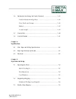
Page 5: ...3 7 Control Box 3 20 3 8 Control Pendant 3 21 Chapter 4 Specifications 4 1 Wire Rope and Lifting Specifications 4 2 4 2 Hoist Specifications by Model 4 3 4 3 Electrical 4 5 Chapter 5 Operation and Se...

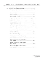
Page 6: ...tension Assembly and Mounting 5 16 Scaff Trac Parts List 5 17 Installing Scaff Trac Monorail 5 17 Scaff Trac Extension Parts List 5 18 Attaching the Scaff Trac Monorail Extension 5 18 Mac Trac Mountin...

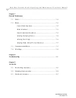
Page 7: ...Hoist on a Monorail Trac System 5 30 5 7 Counterbalancing of Monorail Systems 5 31 Counterbalancing Calculations 5 31 Chapter 6 Maintenance and Care 6 1 Care and Storage 6 2 Motor and Electrical Conn...

Page 8: ...7 2 Brake 7 2 Conical Brake Operation 7 2 Brake Adjustment 7 3 General Adjustment Guidelines 7 4 Adjusting the Spring Tension 7 4 Adjusting the Air Gap 7 4 Adjusting Brake without Previous References...

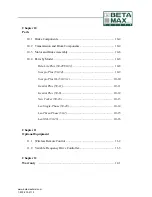
Page 9: ...el 10 8 Beta Lite Plus 50 29 50 31 10 8 Scorpio Plus 50 34 10 9 Scorpio Plus XL 50 33 1 10 10 Gemini Plus 50 11 10 11 Gemini Plus 50 8 10 12 New Yorker 50 18 10 13 Leo Single Phase 50 40 10 14 Leo Thr...

Page 10: ......

Page 11: ...i Plus New Yorker Leo Leo XXL and will note model specific topics where applicable All Beta Max hoists meet or exceed ANSI CSA OSHA and UL specifications Page 1 1 Description 1 2 1 2 Cautions Warnings...

Page 12: ...sing with a sealed lubrication system Gears and bearings operate in an oil bath All Beta Max portable hoists have an emergency UP limit switch which stops the hoist motion when the load has reached th...

Page 13: ...t is used in this manual A WARNING indicates that personal injury or death could result if the WARNING is not followed WARNING Failure to observe a safety instruction noted by WARNING could result in...

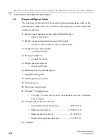
Page 14: ...sockets and wrenches 6 point and 12 point 10 mm 11 mm 12 mm 17 mm 19 mm 22 mm 3 Standard sockets and wrenches 7 16 inch 7 8 inch 4 Flat tip screwdrivers 1 4 inch 3 16 inch 5 Phillips head screwdrivers...

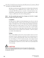
Page 15: ...size of the hose length and gauge of electrical cable The measured voltage at the electrical outlet may be 110V AC or 220V AC with nothing plugged in or just a couple of pieces of equipment running In...

Page 16: ...perage requirements Beta Max suggests no less than 10 gauge 10 3 S O for 110V AC models and 12 gauge 12 3 for 220V AC models Heavier electrical cable is required for Beta Max hoists and will allow a l...

Page 17: ...injury or death Ensure all supporting structures and load attaching devices used in conjunction with this equipment provide an adequate safety factor to handle the rated load plus the weight of the e...

Page 18: ...Introduction and General Description B e t a M a x P o r t a b l e H o i s t s O p e r a t i n g a n d M a i n t e n a n c e P r o c e d u r e s M a n u a l www betamaxhoist com 1 8 1 800 233 5112...

Page 19: ...hout this manual lists safety precautions to follow when operating or working on the machinery and describes machine safety devices This chapter contains the following sections Page 2 1 Safety Respons...

Page 20: ...personnel must use the following safety guidelines and procedures before either operating or working on the Beta Max portable hoist Read and understand the contents of this manual before trying to ope...

Page 21: ...ovide useful additional data but are never used to communicate safety hazards The Attention symbol shows a general safety instruction that is not related to a specific safety point Pay attention to WA...

Page 22: ...or damage caused during installation by the customer Know the location and operation of the emergency stop push button or power disconnects before operating the Beta Max portable hoist Never place han...

Page 23: ...affold The hoist should only be used on flat level roofs or masonry floors When mounting to scaffold the scaffold must be erected to OSHA and ANSI standards Any other use of this equipment voids the m...

Page 24: ...his list Please refer to other source material such as the Occupational Safety and Health Standards OSHA manual the American National Standards Institute ANSI manual and all local national safety regu...

Page 25: ...hoist to lift people DO NOT use the hoist for side lifting loading DO NOT use the hoist remote control if you cannot see the hoist DO NOT use the hoist remote control if you are not in direct communi...

Page 26: ...ng the appropriate safety clothing and equipment F Hoist identification labels tags and plates are not modified in any way or missing F Work area near and around hoist is free from obstructions clutte...

Page 27: ...mer is being used F Electrical power supply cable between the power source and hoist is a minimum size of 10 gauge wire Use of a lighter gauge wire is unacceptable and use of a heavier gauge is recomm...

Page 28: ...maxhoist com 2 10 1 800 233 5112 2 7 Safety Labels Safety labels indicate special hazards in and around the Beta Max portable hoist work area Read all safety labels and follow instructions on them Bel...

Page 29: ...nents but may vary slightly in appearance The five areas discussed are Motor Brake Transmission Drum Wire Rope Shroud and Tops and Control Box Page 3 1 Motor and Brake 3 2 3 2 Transmission and Drum 3...

Page 30: ...20V AC single or three phase electric motor depending on the model and customer choice The motor is fan cooled and all electrical components are sealed and protected from the weather A fail safe conic...

Page 31: ...rmanently lubricated It should be inspected monthly for leaks or damage and should be inspected by a factory service center after the first year of use The gear reduction system is completely enclosed...

Page 32: ...N When using a double wire rope rigging setup be certain the mounting support system is rated for the increased weight that double rope rigging will allow Double rope pulley presents a potential pinch...

Page 33: ...ngth to provide a margin of safe operation The design factor will vary depending upon the type of machine work load and installation The end user operator must determine the applicable design factor b...

Page 34: ...oid With use all wire ropes will wear out The strength of a wire rope begins to decrease when the rope is put in use and continues to decrease with each use Severe abuse and or misuse of the wire rope...

Page 35: ...ury or potential equipment damage NOTE When a wire rope is removed from service because it is no longer suitable for use it must be discarded and never reused on any application A typical daily wire r...

Page 36: ...mage a wire rope Lack of lubrication can significantly shorten the useful service life of a wire rope Contact with electrical wires high voltage and arcing will damage a wire rope WARNING Never use a...

Page 37: ...ase read and follow all information provided on the shroud labels and identification plates before operating the hoist for important safety and cautionary information The identification plates indicat...

Page 38: ...eam mounting top is simply bolted to the I Beam and keeps the hoist in a set position The Rolling I Beam Trolley Top mounts to an existing I Beam and has rollers to allow free movement of the hoist al...

Page 39: ...handle the hoist with care when transporting and mounting to avoid equipment damage Do not allow any part of the hoist to be battered against other objects Only use the handles to carry the hoist and...

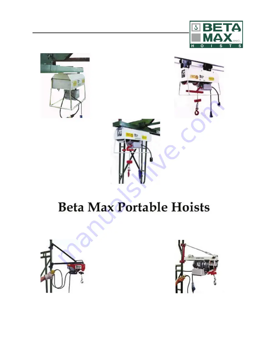
Page 40: ...formed The six available options are Vertical Post Sliding Trolley Scaff Trac Mac Trac Trestle Monorail and I Beam Provided below is a table showing the different models and what type mounting option...

Page 41: ...easily hold the hoist in place The pivot mount allows 180 degree movement for maximum flexibility of load movement Vertical post mounts can be either top or bottom supported For use on Beta Lite Scorp...

Page 42: ...o c e d u r e s M a n u a l www betamaxhoist com 3 14 1 800 233 5112 Sliding Trolley A variation of the Vertical Post mount the Sliding Trolley adds a five foot 1 5 meter cantilever with a sliding tr...

Page 43: ...with 8 foot 2 4 meter cross braces and has a 2 5 foot 0 8 meter cantilever The Scaff Trac monorail is attached to the scaffold with two saddles safety pins and keepers that fit on top of the scaffold...

Page 44: ...orkload can be pulled in by hand and set down on a work platform For lifting larger loads the system can be adjusted to raise material up through the center of the scaffold to the work platform The Ma...

Page 45: ...www betamaxhoist com 1 800 233 5112 3 17 Figure 3 11 Mac Trac...

Page 46: ...and keepers and a 3 5 foot 1 1 meter cantilever The Trestle Monorail must be anchored in one of the following four ways for safe hoist operation trestle ceiling brace floor tie down clamps ballast con...

Page 47: ...s to the anchor bolts Ballast A counterbalance or ballast system uses two rigid metal containers each with a capacity of 9 5 cubic feet 269 liters bolted to the inboard rear Trestle Monorail leg The w...

Page 48: ...bly the control box serves as the central power receiving and sending station for the portable hoist Electrical power is supplied to the control box through the electrical power source cable Power is...

Page 49: ...meter electrical cable Optional remote control cable extensions are available in either 25 feet 7 6 meter or 85 feet 25 9 meter for all models Optional control pendants include dual remote controls a...

Page 50: ...Components B e t a M a x P o r t a b l e H o i s t s O p e r a t i n g a n d M a i n t e n a n c e P r o c e d u r e s M a n u a l www betamaxhoist com 3 22 1 800 233 5112...

Page 51: ...apter will cover Beta Max portable hoist specifications including wire rope lifting capacities power requirements unit weights and additional electrical information Page 4 1 Wire Rope and Lifting Spec...

Page 52: ...ns by Model Model Rope Diameter Max Lifting Capacity Single Rope Maximum Lifting Capacity Double Rope Maximum Lifting Height Single Rope Maximum Lifting Height Double Rope Beta Lite 5 32 inch 3 969 mm...

Page 53: ...ds 13 6 kg 46 pounds 20 9 kg Scorpio Plus 80 fpm 110V AC 15 Amps 80 pounds 36 3 kg 96 pounds 43 5 kg Scorpio Plus XL 80 fpm 110V AC 15 Amps 90 pounds 40 8 kg 102 pounds 46 3 kg Gemini Plus 80 fpm sing...

Page 54: ...supplied with the hoist Never replace wire rope with any different specifications without first contacting and consulting the dealer or Beta Max Inc If wire rope specifications are not known contact...

Page 55: ...e control relays This UP limit switch is an emergency safety shutoff and should never be used as a substitute for stopping upward motion Push button controls are deadman type and work on 24V DC circui...

Page 56: ...Specifications B e t a M a x P o r t a b l e H o i s t s O p e r a t i n g a n d M a i n t e n a n c e P r o c e d u r e s M a n u a l www betamaxhoist com 4 6 1 800 233 5112...

Page 57: ...a Max portable hoists and various mounting systems Page 5 1 Operating the Hoist 5 2 5 2 Single Rope Rigging 5 4 5 3 Double Rope Rigging 5 5 5 4 Mounting System Setups and Installations 5 6 5 5 Methods...

Page 58: ...oist See Shrouds and Mounting Tops and Mounting Hoist on a Monorail Trac System for details 2 Press the control pendant DOWN push button to lower the cable 3 Release the push button to stop the cable...

Page 59: ...ause the load to rotate slightly in one direction The non rotational qualities of the rope will stop this rotation and the rope and load will seek a natural balanced state Load rotation may occur due...

Page 60: ...k at the end of the cable to the load For wire rope and hoist maximum load lifting capacities see Table 4 1 Maximum Working Load Capacity Every wire rope user should be aware of the fact that each typ...

Page 61: ...e 8 inch pulley hook 4 Remove the wheel 5 Insert the cable around the wheel 6 Reinstall the pulley wheel and center bolt Be sure to secure the bolt with the safety clip provided This bolt MUST be secu...

Page 62: ...post mount Post mounting is simple and quick The following represents different vertical post mounting options Between Floor Mount For use at the edge of balconies or just inside doors where both the...

Page 63: ...www betamaxhoist com 1 800 233 5112 5 7 Figure 5 2 Vertical Post Mounting Shown with Scorpio Plus XL Hoist...

Page 64: ...and use a level to make sure the hoist is completely horizontal and level with the ground This will ensure proper spooling of the wire rope on the drum Assembly Installation of Scaffold Post Mount Sy...

Page 65: ...counterweight to use see the formula below When mounting to a scaffold using a vertical post mount use a 1 1 design factor This means that the counterweight must equal the weight of the hoist and the...

Page 66: ...the rolling I Beam Trolley Top for applications that require horizontal rolling movement of the hoist and load The other option is the Fixed I Beam Top for attaching a portable hoist to an I Beam whe...

Page 67: ...I Beam suspension brackets are designed to attach to the top of a steel I Beam and pull it up tight against the underside of the scaffold frame horizontal ledger The spacing between the top and botto...

Page 68: ...a n c e P r o c e d u r e s M a n u a l www betamaxhoist com 5 12 1 800 233 5112 Figure 5 5 I Beam Suspension Brackets Table 5 1 I Beam Suspension Bracket Parts List Item Description A Saddle B I Bea...

Page 69: ...or variations in scaffold frames 2 Connect one mounting bracket B at the location on the I Beam to match up with the saddle connecting point 3 Raise both ends of the I Beam C to the under side of the...

Page 70: ...al or national safety requirements Scaffold frames must be in good condition and free of dents bends heavy corrosion cuts modifications or any other damage All cross braces must be in place and secure...

Page 71: ...ot Model 60 41 Special 8 foot Model 60 11 Extension Used on 7 foot scaffold 8 foot scaffold 7 foot scaffold Load Bearing Capacity 1200 pounds 544 kg 1200 pounds 544 kg 1200 pounds 544 kg Unit Weight 1...

Page 72: ...b l e H o i s t s O p e r a t i n g a n d M a i n t e n a n c e P r o c e d u r e s M a n u a l www betamaxhoist com 5 16 1 800 233 5112 Scaff Trac and Scaff Trac Extension Assembly and Mounting Figu...

Page 73: ...riations in scaffold frames 2 Raise both ends of the Scaff Trac Monorail Trac B to the under side of the saddles A 3 Insert the pins and keepers C into the same set of holes on each saddle 4 Once the...

Page 74: ...extension is added Multiple extensions can be added to the system as needed 1 Place the saddle A over the next scaffold frame on the inboard side of the previously mounted Scaff Trac B 2 Lift the outb...

Page 75: ...ters A full width deck must be installed at the hoist location to provide adequate working room and footing for installing and operating the hoist The scaffold must be horizontally level Check the sca...

Page 76: ...a n d M a i n t e n a n c e P r o c e d u r e s M a n u a l www betamaxhoist com 5 20 1 800 233 5112 Figure 5 7 Mac Trac Components Table 5 4 Mac Trac Parts List Item Description A 7 foot horizontal b...

Page 77: ...maxhoist com 1 800 233 5112 5 21 Figure 5 8 Example of Mac Trac Setup Mac Trac Parts List 1 Two 7 foot horizontal braces A 2 One 7 foot Mac Trac Monorail Trac B 3 Four retaining clips C 4 Two retainin...

Page 78: ...fold with J hook clamps 6 Braces have three sets of holes for mounting the Monorail Trac Choose the desired location left center or right 7 Lift up the Mac Trac Monorail Trac B and align the mounting...

Page 79: ...assemble the system at the same location of intended installation An alternative method is to put the system together in one place and transport the assembled unit to the installation area The Trestle...

Page 80: ...ation and Setup B e t a M a x P o r t a b l e H o i s t s O p e r a t i n g a n d M a i n t e n a n c e P r o c e d u r e s M a n u a l www betamaxhoist com 5 24 1 800 233 5112 Figure 5 9 Trestle Mono...

Page 81: ...g capscrews E Hand tighten only This is a temporary support step 3 Join the free end of the other two braces D together on the other side in the center using capscrews E Hand tighten only This is a te...

Page 82: ...s E 12 Hand tighten the nuts 13 Repeat Steps 11 12 for the other side 14 Measure the distance between both uprights in two places left and right sides to ensure the unit is square If the measurements...

Page 83: ...e Monorail is nearly identical with the 1200 pound 544 kg capacity model with the exception of the following steps Therefore follow Steps 1 11 for the 1200 pound 907 kg Capacity Trestle Monorail first...

Page 84: ...ce Use this method when the Trestle Monorail will be installed on an intermediate floor of a building with a rigid structural ceiling above After the Trestle Monorail is assembled and placed in the de...

Page 85: ...ts Suggested materials to use for ballast are bricks solid concrete blocks stone or other high density nonflow material Liquids can not be used and loose sand in some installations may not be a suitab...

Page 86: ...onorail Trac 2 Raise the hoist and roll it into the Monorail Trac 3 Reinstall the retaining pin or bolts at the end of the Monorail Trac to prevent the hoist from rolling out CAUTION When installing t...

Page 87: ...ensure that the scaffold components are NOT distorted or separated Counterbalancing Calculations For safe equipment operation the proper amount of counterweight must be calculated and applied The Tres...

Page 88: ...terbalance the system When mounting to Vertical Post The Vertical Post type system requires very little to calculate the required weight to counterbalance the system Simply add the weight of the hoist...

Page 89: ...om 1 800 233 5112 6 1 Chapter 6 Maintenance and Care This chapter will cover the maintenance and care for Beta Max portable hoists Page 6 1 Care and Storage 6 2 6 2 Removal of Wire Rope 6 4 6 3 Instal...

Page 90: ...e careful not to damage the motor housing cooling fans If the fins are broken have the motor examined immediately by a qualified technician Do not allow the pendant control switch to become submerged...

Page 91: ...d is maintenance free A monthly inspection for leaks and housing damage is recommended After the first year of use Beta Max suggests an inspection by a factory service center Roller Mounting Tops Insp...

Page 92: ...rs and hands away from drum when hoist is operating CAUTION Always wear heavy gloves when handling the wire rope to prevent possible hand injury 1 Remove the headache ball weight thimble and hooks fro...

Page 93: ...ting and consulting the dealer or Beta Max Inc If wire rope specifications are not known contact Beta Max Inc with the proper model and serial number to verify correct wire rope specifications for the...

Page 94: ...um and pull the rope through the side cavity hole of the drum 4 If using Nicopress fittings slip the copper sleeve over the nonterminated end of the wire rope and crimp three times with a crimping too...

Page 95: ...t com 1 800 233 5112 7 1 Chapter 7 Periodic Maintenance This chapter will cover the periodic maintenance for Beta Max portable hoists Page 7 1 Motor 7 2 7 2 Brake 7 2 7 3 Transmission and Drum 7 7 7 4...

Page 96: ...afe conical braking system provides safe load handling at any lifting position and securely holds the load even when electrical power is lost This system operates from the inductive forces in the roto...

Page 97: ...r gap adjustment The tension spring adjustment controls the amount of force applied to press the brake into the brake end cap and provides load holding ability The air gap adjustment sets the distance...

Page 98: ...on turn the tension adjustment locknut 6 clockwise NOTE The tension adjustment locknut 6 has left handed threads Adjusting the Air Gap The nominal recommended air gap is 0 025 inches 0 635 mm When adj...

Page 99: ...www betamaxhoist com 1 800 233 5112 7 5 Figure 7 1 Conical Brake Exploded View...

Page 100: ...tamaxhoist com 7 6 1 800 233 5112 Table 7 1 Brake Components Item Description 1 Rotor 2 Tension Pin 3 Tension Spring 4 Tension Shaft 5 Washer 6 Tension Adjustment Locknut 7 Brake 8 Inner Air Gap Adjus...

Page 101: ...screws 14 until the outer bearing surface 9 comes in contact with the inner side of the outer air gap adjustment ring 12 The air gap clearance at this point should be zero 5 Increase the air gap by t...

Page 102: ...lube generously not dripping applied with a shop towel WARNING Always wear heavy gloves when handling the wire rope to prevent possible hand injury Never place hand between UP limit bar and drum Beta...

Page 103: ...pressing either the UP or DOWN push buttons hoist motor makes no sound No electrical power LED not lit Unit has been used continuously for more than 20 minutes and has exceeded the recommended 50 per...

Page 104: ...needs adjustment Load is heavier than the rated maximum for the model being used Capacitor damage or capacitor malfunction Check for correct voltage at the motor with the hoist loaded and lifting Adj...

Page 105: ...will not operate when pressing either the UP or DOWN push buttons motor hums Brake needs adjustment Capacitor damage or malfunction No electrical power LED not lit Adjust the brake Test capacitors an...

Page 106: ...the upper limit bar Upper limit bar is bent Position the load directly below the hoist and lift straight up Never pull or drag the load from the side DO NOT USE TAG LINES Repair or replace the upper l...

Page 107: ...800 233 5112 9 1 Chapter 9 Accessories This chapter will cover the accessories available for Beta Max portable hoists Page 9 1 Hoist Lifting Accessories 9 2 9 2 Mounting Top Accessories 9 6 9 3 Elect...

Page 108: ...233 5112 9 1 Hoist Lifting Accessories Beta Max Inc offers a wide range of lifting accessories to accommodate many specialized lifting demands Brick Fork 400 pound 182 kg capacity Maximum brick size...

Page 109: ...36 1 4 L x 15 W x 25 H Holds 10 scaffold frames Basket with Spreader Bar 400 pound 182 kg capacity Dimensions 30 3 4 L x 20 3 4 W x 12 1 4 H 800 pound 363 kg capacity Dimensions 36 3 4 L x 36 3 4 W x...

Page 110: ...n u a l www betamaxhoist com 9 4 1 800 233 5112 Dumpster Bucket Easy to empty swivels through 360 degree arc Available in 24 31 or 40 gallon capacity Wheelbarrow Sling Regular 400 pound 182 kg capaci...

Page 111: ...capacity Dimensions 42 L x 27 W x 28 H Double Rope Kit A rugged pulley and hook assembly designed for units with double rope capabilities Counterweight Clamp Assembly Easily attaches to Trestle Monor...

Page 112: ...Beam Trolley Top Provides the ability to easily move the hoist and workload from the lifting point to the work area Rollers are permanently sealed and are maintenance free Adjustable to fit flange wi...

Page 113: ...ly to extend the working range from the hoist Quick disconnects attached to both ends Available in 25 foot 7 6 meter and 85 foot 25 9 meter lengths Booster Transformer For use when power supply cable...

Page 114: ...tamaxhoist com 9 8 1 800 233 5112 Pendant Assembly Push button control with a quick disconnect for raising and lowering the workload Attached 6 foot electrical cable Power Cord Extension 110V AC or 22...

Page 115: ...5112 10 1 Chapter 10 Parts This chapter will cover the parts used on Beta Max portable hoists Page 10 1 Brake Components 10 2 10 2 Transmission and Drum Components 10 4 10 3 Motor and Brake Assembly...

Page 116: ...t a M a x P o r t a b l e H o i s t s O p e r a t i n g a n d M a i n t e n a n c e P r o c e d u r e s M a n u a l www betamaxhoist com 10 2 1 800 233 5112 10 1 Brake Components Figure 10 1 Brake Co...

Page 117: ...on 1 Rotor 2 Tension Pin 3 Tension Spring 4 Tension Shaft 5 Washer 6 Tension Adjustment Locknut 7 Brake 8 Inner Air Gap Adjustment Ring 9 Bearing 10 Bearing Locknut 11 Motor Brake End Cap 12 Outer Air...

Page 118: ...P o r t a b l e H o i s t s O p e r a t i n g a n d M a i n t e n a n c e P r o c e d u r e s M a n u a l www betamaxhoist com 10 4 1 800 233 5112 10 2 Transmission and Drum Components Figure 10 2 Tr...

Page 119: ...2 10 5 Table 10 2 Transmission and Drum Item Description 1 Retaining Ring 2 Cogged Wheel 3 Bearing 4 Cogged Wheel 5 Key 6 Intermediate Shaft 7 Shell 8 Spacer 9 Bearing 10 Retainer Ring 11 Oil Seal 12...

Page 120: ...x P o r t a b l e H o i s t s O p e r a t i n g a n d M a i n t e n a n c e P r o c e d u r e s M a n u a l www betamaxhoist com 10 6 1 800 233 5112 10 3 Motor and Brake Assembly Figure 10 3 Motor an...

Page 121: ...Spacer 5 Packed Casing 6 Oil Splash Guard 7 Inner Flange 8 Front Bearing 9 Rotor Shaft 10 Terminal Unit 11 Terminal Unit Cover 12 Fan Cover Plug 13 Tie Rod 14 Adjusting Ring Nut 15 Rear Shield 16 Aut...

Page 122: ...e t a M a x P o r t a b l e H o i s t s O p e r a t i n g a n d M a i n t e n a n c e P r o c e d u r e s M a n u a l www betamaxhoist com 10 8 1 800 233 5112 10 4 Parts by Model Beta Lite Plus 50 29...

Page 123: ...www betamaxhoist com 1 800 233 5112 10 9 Scorpio Plus 50 34...

Page 124: ...Parts B e t a M a x P o r t a b l e H o i s t s O p e r a t i n g a n d M a i n t e n a n c e P r o c e d u r e s M a n u a l www betamaxhoist com 10 10 1 800 233 5112 Scorpio Plus XL 50 33 1...

Page 125: ...www betamaxhoist com 1 800 233 5112 10 11 Gemini Plus 50 11...

Page 126: ...Parts B e t a M a x P o r t a b l e H o i s t s O p e r a t i n g a n d M a i n t e n a n c e P r o c e d u r e s M a n u a l www betamaxhoist com 10 12 1 800 233 5112 Gemini Plus 50 8...

Page 127: ...www betamaxhoist com 1 800 233 5112 10 13 New Yorker 50 18...

Page 128: ...Parts B e t a M a x P o r t a b l e H o i s t s O p e r a t i n g a n d M a i n t e n a n c e P r o c e d u r e s M a n u a l www betamaxhoist com 10 14 1 800 233 5112 Leo Single Phase 50 40...

Page 129: ...www betamaxhoist com 1 800 233 5112 10 15 Leo Three Phase 50 2...

Page 130: ...Parts B e t a M a x P o r t a b l e H o i s t s O p e r a t i n g a n d M a i n t e n a n c e P r o c e d u r e s M a n u a l www betamaxhoist com 10 16 1 800 233 5112 Leo XXL 50 25...

Page 131: ...st com 1 800 233 5112 11 1 Chapter 11 Optional Equipment This chapter will cover optional equipment for Beta Max portable hoists Page 11 1 Wireless Remote Control 11 2 11 2 Variable Frequency Drive Co...

Page 132: ...ontrolled hoist follow these steps 1 Unplug the standard 6 foot operator s pendant 2 Hang the wireless remote control box on the back side of the hoist shroud using the two hangers supplied with the w...

Page 133: ...while operating on single or three phase power The VFD controller provides for soft start and stop operation and allows a slow acceleration deceleration to avoid shocking the load The standard configu...

Page 134: ...Optional Equipment B e t a M a x P o r t a b l e H o i s t s O p e r a t i n g a n d M a i n t e n a n c e P r o c e d u r e s M a n u a l www betamaxhoist com 11 4 1 800 233 5112...

Page 135: ...returned to Beta Max Inc through an authorized distributor The warranty period shown below begins on the date the equipment is sold to the original purchaser Any return shipments to Beta Max Inc must...

Page 136: ...anty Distributors must get a return authorization number from Beta Max Inc before any item is returned for repair or replacement The obligation of Beta Max Inc is limited to replacing parts and does n...

Page 137: ...___________________________ __________________________________________________________________________ __________________________________________________________________________ ______________________...

Page 138: ......

Page 139: ......

Reviews: