


Installation Instructions for IDH Max 1300 Mortise Locks
BEST ACCESS SYSTEMS
A Division of Stanley Security Solutions, Inc
9
Installation Instructions for IDH Max 1300 Mortise Locks
Installing the lock
9
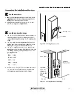
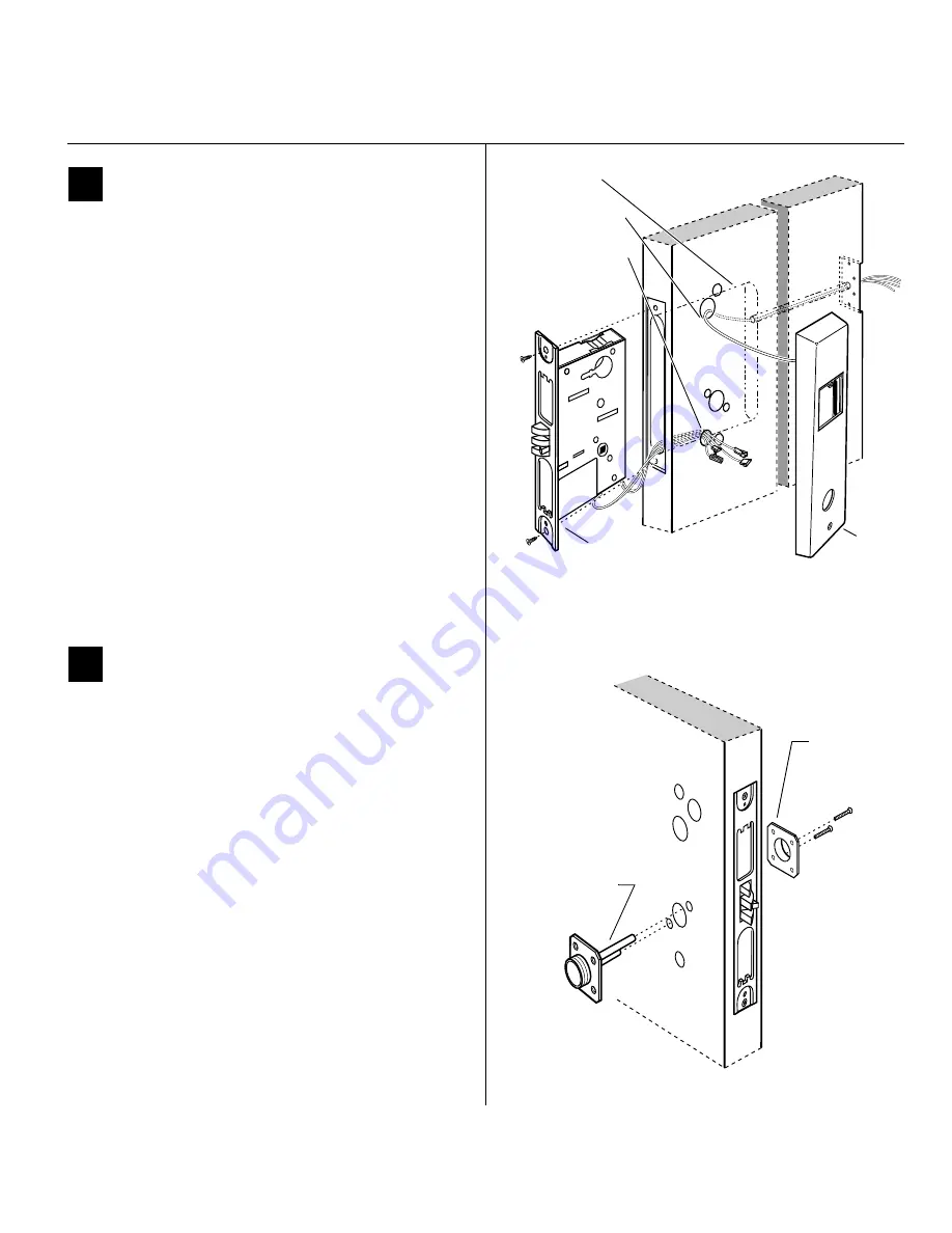
Install mortise case
1 Remove the faceplate from the mortise case.
2 Insert the mortise case into the mortise cavity, while
feeding the sensor and solenoid wires into the mortise
cavity and out the sensor & solenoid wire hole to the
inside of the door.
Note:
The field wire harness should be routed above and
behind the mortise case (depending on where the hole
through the door meets the mortise cavity).
3 Make sure there are 3
″
to 4
″
of slack in the field wire
harness to allow access to the control electronics cir-
cuit board in the inside trim.
4 Secure the mortise case with the case mounting
screws.
10
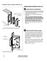
Install mounting plates
1 Insert the outside mounting plate through the door
and mortise case.
2 Position the inside mounting plate opposite the out-
side mounting plate and screw them securely in place.
Caution:
Do not overtighten the mounting plate
screws. Overtightening may compress the mortise
cavity and bind the locking mechanism.
Figure 9
Installing the mortise case
Inside of door
Field wire harness
Inside
trim
Sensor & solenoid
wire hole and wires
Mortise
case
Mortise cavity
Figure 10 Installing the mounting plates
Outside of door
Outside
mounting plate
Inside
mounting
plate