Berthoud COSMOS 18 PRO Assembly Manual Download Page 3

Page 3  


FR : DROITIER   

GB: RIGHT HANDED USE 

SP: DIESTRO 

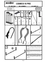
ETAPE 2 : Fixation du levier sur le balancier et 
mise en place de la bielle 
A : Mettre en place le levier n°3 à l’extérieur du 
balancier n°1 en alignant la forme et les trous. 

2 A 

n°3 

n°1 

n°4 

n°5 

n°7 

n°6 

STEP 2 : Fix lever to the beam and assemble the 
connecting rod 
A : Place lever n°3 alongside beam n°1 lining up 
the edges and the holes. 
 

ETAPA  2 : Fijación de la palanca sobre el 
balancín y montaje de la biela 
A : Colocar  la palanca n°3 al exterior del 
balancín n°1 alineando la forma y los huecos 

B : Insérer une vis n°4 à travers le balancier (une 
seule vis n°4 est utilisée pour la version droitier). 

B : Insert screw n°4 into the beam (only one 
screw n°4 is required for the right handed use) 

B : Insertar un tornillo n°4 a través del balancín 
(Se usa un solo tornillo n°4 para la versión 
diestro) 

C : Insérer la rondelle n°5, la rondelle n°6 et 
l’écrou n°7 autour de la vis n°4. Serrer l’écrou 
n°7 au maximum. 
 

C : Place washer n°5, washer n°6 and nut n°7 
around the screw n°4. Tighten nut n°7 to 
maximum. 

C : Insertar la arandela n°5, la arandela n°6 y la 
tuerca n°7 en torno al tornillo n°4. Apretar la 
tuerca n°7 al máximo. 

n°4 

2 B 

n°3 

n°1 

n°3 

2 C 

n°3 

Summary of Contents for COSMOS 18 PRO

Page 1: ...n 9 x 1 n 11 x 1 n 10 x 1 n 12 x 1 n 13 x 1 n 6 x 2 n 16 x 2 n 14 x 1 ETAPE 1 Montage du balancier Selon mod le A Ecarter au maximum les l ments de fixation de la tige STEP 1 Assembly of the beam Dep...

Page 2: ...eur extr mit dans l encoche pr vue cet effet Selon mod le D Slide the bearings item n 2 to the ends of the rod to clip them into the slots provided Depending on the model D Hacer deslizar las piezas n...

Page 3: ...rior del balanc n n 1 alineando la forma y los huecos B Ins rer une vis n 4 travers le balancier une seule vis n 4 est utilis e pour la version droitier B Insert screw n 4 into the beam only one screw...

Page 4: ...onarla en frente del hueco de la palanca n 3 F Ins rer la tige n 8 dans le trou du levier n 3 Fin du montage pour droitier passer l tape 3 page 7 F Insert rod n 8 into lever hole n 3 Go to step 3 on p...

Page 5: ...ar la palanca n 3 lado tap n al exterior del balanc n alineando la forma y los huecos B Ins rer les 2 vis n 4 travers le balancier B Insert 2 screws n 4 into the beam B Insertar los 2 tornillos n 4 a...

Page 6: ...in front of beam hole n 1 E Hacer pivotar la varilla n 8 para posicionarla en frente del hueco del balanc n n 1 2E STEP 3 Assemble the mixer tap Insert mixer tap n 9 into the tank and clip it onto th...

Page 7: ...STEP 4 Attach the tubing onto the pump A Slide the sealing ring n 17 onto hose n 10 Make sure you attach the sealing ring the right way round as shown B Attach the hose onto hose connector n 19 turn...

Page 8: ...ar la tuerca al m ximo 5D n 11 n 10 n 12 ETAPE 6 Montage des bretelles A Mettre les bretelles plat en positionnnant les passants de sangles sur le dessus puis glisser la partie centrale des bretelles...

Page 9: ...pieza n 16 dentro de cada hebilla del tirante luego correr cada tirante para bloquearlos 6D x2 x2 n 16 n 14 n 14 ETAPE 7 R glage des bretelles R gler la longueur des bretelles votre convenance l aide...

Page 10: ...little or no spray the nozzle wand and filter servicing points the tightness of plunger tube G on the cap of the air chamber No pressure build up in the air chamber the air chamber servicing points th...

Page 11: ...de mantenimiento relativos a la boquilla lanza filtros la impermiabilidad del tubo de inmersi n G sobre la tapa de la campana de aire No existe presi n en la campana de aire los puntos de mantenimient...

Page 12: ...uncionamento Depois de despressurizar o aparelho verificar A camp nula de ar est sob press o mas a n o h pulveriza o ou deficiente os pontos de manuten o relativos ao aspersor lan a aos filtros a esta...

Reviews: