FlowStar2 LB 514
3. Measuring Cells
33
3.2 Assembly and Disassembly of Measuring Cells
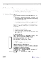
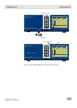
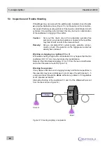
The measuring cells have been designed as a module for easy installation
(and replacement) from the front of the monitor (see Figure 6). The module
is fixed by 2 socket head cap screws size M 4 x 12 mm. (The screws and
the respective screwdriver are included with the shipment.)
Each measuring cell includes a chip that offers two functions:
When it is inserted, it automatically established contact when the meas-
uring cell is fixed with screws, and cuts the contact again as soon as
the screws of the measuring cell are released. This ensures that the
high voltage is turned on only if the counting chamber is closed.
It informs the system about the parameters of the measuring cell. This
ensures that only methods can be used during a run which are suitable
for this measuring cell.
Figure 6: Front view of FlowStar² Monitor
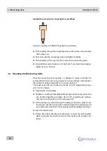
Light seal and incidence of light
An O-ring seal (59 x 2 mm) protects the measuring chamber against light.
Make sure the seal is clean and seated properly in the groove of the count-
ing chamber!
The base plate of the cells should be clean and without any alien materials
(e.g. labels)!
Spare O-rings are included as accessories.
FlowStar LB 514
2
Status
READY
Cell
Test 14C
LS-Pump
OFF
Time HH:mm:ss
ELAPSED 00:00:00
125.4
20
10
0
0
2
4
6
8
CPM
C-14
I
O
Status
READY
Cell
Test 14C
LS-Pump
OFF
Time HH:mm:ss
ELAPSED 00:00:00
125.4
20
10
0
0
2
4
6
8
CPM
C-14

