background image


6

To convert the regulator for use with the other gas different from which one it is pre-arranged it is enough 
perform the following operations: 

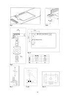
1) Unscrew by hand the upper metal stopper of the regulator (Fig. 5). 

2) Unscrew by hand the white plastic piece screwed under the above mentioned metal stopper, afterward 
screw it again in opposite way under the metal stopper (for gas reference see the written “LP” and “NAT” with 
relative indicating arrows on the white piece). 

3) Screw again by hand the metal stopper in the original position on the regulator. 

Operating in this way the gas regulator is converted for use with the other gas/pressure. 

Descriptions 

DESCRIPTIVE CAPTION FOR HOB 

DESCRIPTION OF HOB: 

Fig.9


1. Small Burner  


2. Medium burner 


3. Rapid burner 


4. Double ring (wok) burner 


5. Fish burner 


6. Front left side burner control knob 
7. Front right side burner control knob 
8. Back left side burner control knob 
9. Back right side burner control knob 
10. Middle burner control knob 

Service & maintenance instructions 

Service and maintenance only to be carried out by an authorised person 

To replace parts such as burners, valves and electric components, the hotplate must be removed from the 
bench top by releasing the attachment hooks, loosening the attachment screws of each burner, unscrewing 
the hotplate attachments nuts which are visible at the bottom of the surface, removing the hotplate top and 
finally replacing the defective parts. 

Note:

 if the valves must be replaced, first disassemble the ignitions switches wires. 

It is recommended to replace the valve gaskets each time the valve is replaced, thus ensuring a perfect seal 
between the body and the gas train. 

WARNING: Disconnect power before servicing unit. 

For the location of the wall receptable for the connection of the three-pin earthed plug of the 
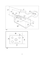
appliance, see indications given in Fig. 1,  2  

WARNING: After first installation of the appliance or after any service intervention concerning main 
gas parts of the appliance, make the leak test using water with soap on the gas connections in order 
to verify the correct installation. Do not use fire for gas leak testing. 

 
Greasing the valves


If it becomes difficult to operate the valve, it should be greased immediately by following the instructions 
listed below 
1. Disassemble the valve body by loosening the two screws located on the body of the valve. (See Fig. 11). 
2. Extract and clean the seal cone and its housing with a rag soaked with thinners. 
3. Lightly grease the cone with a special grease. 
4. Insert the cone, moving it several times, remove it again, remove the excess grease and make sure that 
the gas passage ways are unobstructed. 
5. Replace all the pieces in reverse order and check that the valve operates correctly. 

User instructions 

WARNINGS:


Keeping appliance area clear and free from combustible materials, gasoline and other flammable 
vapors and liquid. 

Summary of Contents for P310..L4X(2 OR 5)D

Page 1: ...ny electrical switch Do not use any phone in your building Immediately call your gas supplier from a neighbor s phone Follow the gas supplier s instructions If you cannot reach your gas suppliers call the fire department Installation and service must be performed by a qualified installer service agency or the gas supplier Read this instruction booklet before installing and using the appliance The ...

Page 2: ...cally grounded in accordance with local codes or in the absence of local codes with the National Electrical Code ANSI NFPA 70 The appliance and its individual shutoff valve must be disconnected from the gas supply piping system any pressure testing of that system at test pressure in excess of psi 3 5 kPa The appliance must be isolated from the gas supply piping system by closing its individual man...

Page 3: ...side clearances shall be in accordance with the minimum values indicated in the table n 1 and are shawn and in the fig 1 2 The cooking surface area is defined as that part of the appliance where cooking normally takes place and does not include those parts of the appliance containing control knobs Table n 1 Hobs models P310 Hobs models P310 Min Clearances inches mm Min Clearances inches mm L1 18 5...

Page 4: ...d re check for leaks If it is not possible to correct the leak replace fitting Under no circumstances use matches or flame for checking leaks 7 To checking inlet pressure at the appliance operate as follow a Disconnect electric power before pressure checking be carried out b Take off one of the gas burner cap and the relative flame spreader in order to get access to the burner injector c Put in po...

Page 5: ...4 10400 3047 3700 1084 Regulated Rapid Front L 0 92 LP Propane 11 10400 3047 3700 1084 0 58 1 65 Natural 4 11900 3487 5300 1553 Regulated Triple Ring Central 1 02 LP Propane 11 12300 3604 5300 1553 0 73 CAUTION save the orifices removed from the appliance for future use Regulation of burners Regulation of the MINIMUM on the burners To regulate the minimum on the burners carry out the following pro...

Page 6: ...e at the bottom of the surface removing the hotplate top and finally replacing the defective parts Note if the valves must be replaced first disassemble the ignitions switches wires It is recommended to replace the valve gaskets each time the valve is replaced thus ensuring a perfect seal between the body and the gas train WARNING Disconnect power before servicing unit For the location of the wall...

Page 7: ...s not remain alight after releasing the knob repeat the above procedure Note It is recommended not to try to ignite the burner if the relative flame cap is not in the correct position Tips for using burners correctly WARNING During use of each gas burner s adjust the burner flame size properly so it does not extend beyond the edge of the cooking utensil This is an instruction based on safety consi...

Page 8: ...quest the assistance of the technical service personnel Cleaning the enamelled parts Enamelled parts should be cleaned frequently with soapy water Never use abrasive powder Do not leave acidic or alkaline substances on the enamelled parts such as vinegar lemon juice salt tomato sauce etc and do not wash the enamelled parts while they are still hot Cleaning the stainless steel parts Clean the parts...

Page 9: ...e service Dealer Importer Name address phone MANUFACTURER BERTAZZONI SPA VIA PALAZZINA 8 42016 GUASTALLA REGGIO E ITALY Tel 0522 226411 telefax 0522 226440 http www bertazzoni italia com SERVICE CENTERS Name Phone ...

Page 10: ...eur électrique N utilisez aucun téléphone dans votre établissement Appelez immédiatement votre fournisseur de gaz par le téléphone d un voisin Suivez les instructions du fournisseur de gaz Si vous ne pouvez pas atteindre vos fournisseurs de gaz appelez les pompiers L installation et le service doivent être exécutés par un installateur qualifié une agence de service ou par le fournisseur du gaz Lis...

Page 11: ...pression a un filetage au pas du gaz femelle de Vous devrez déterminer le raccordement demandé selon la dimension du conduit d amenée des gaz du connecteur en métal flexible et du robinet d arrêt L appareil lorsqu il est installé doit être mis à la terre selon les codes locaux ou en l absence de ceux ci avec le National Electrical Code ANSI NFPA 70 L appareil et son robinet d arrêt individuel doiv...

Page 12: ... fabricant Cependant dans aucun cas la distance entre la partie supérieure du brûleur le plus haut de l appareil de cuisson et la hotte d aspiration devra être inférieure au 30 762mm Voir la Fig 1 2 N importe quelle autre surface combustible orientée vers le bas à moins de 600mm vers la partie supérieure du brûleur le plus haut devra être protégée pour sa largeur complète et profondeur de la zone ...

Page 13: ...limentation du gaz et après avoir effectué tous les branchements contrôlez soigneusement les éventuelles fuites Tournez tous les boutons de commande de l unité sur la position OFF Ouvrez la valve sur l alimentation du gaz En utilisant une solution avec du savon et de l eau contrôlez tous les branchements du gaz un après l autre en frottant la solution sur le raccord La présence de bulles indiquera...

Page 14: ...dans le TABLEAU A ci dessous TABLEAU A Adaptation aux différents types de gaz Brûleur Position Diam inj Type Pression Classe Nominale Classe réduite By pass gaz i w c BTU h W BTU h W diam mm 0 90 Naturel 4 3400 996 900 264 Régulation Auxiliiari Avant Droit 0 54 LP Propane 11 3400 996 900 264 0 29 Semi Postérieur 1 18 Naturel 4 6100 1787 1500 439 Régulation Rapide Droit et Gauche 0 70 LP Propane 11...

Page 15: ...r petit 2 Brûleur moyen 3 Brûleur rapide 4 Brûleur double couronne poêle chinoise 5 Brûleur poisson 6 Bouton de commande du brûleur frontal à gauche 7 Bouton de commande du brûleur frontal à droite 8 Bouton de commande du brûleur arrière à gauche 9 Bouton de commande du brûleur arrière à droite 10 Bouton de commande du brûleur central Instructions de service et d entretien Le service et l entretie...

Page 16: ...de panne de courant prolongée Tournez le bouton qui correspond au brûleur choisi dans le sens contraire des aiguilles d une montre dans la position de MAXIMUM à l étoile gravée flamme large et mettez une allumette allumée sur le brûleur Allumage électrique automatique Tournez le bouton qui correspond au brûleur choisi dans le sens contraire des aiguilles d une montre à la position de MAXIMUM à l é...

Page 17: ...tion additionnelle par exemple en ouvrant une fenêtre ou en augmentant la puissance du ventilateur à tirage d air hotte d aspiration si installés Nettoyage de l appareil N utilisez jamais de produits à nettoyer abrasifs Avant de nettoyer l appareil il doit être débranché du réseau électrique Nettoyage de la surface de travail nettoyez périodiquement les têtes des brûleurs les supports en acier éma...

Page 18: ... vente Revendeur Importateur Nom adresse téléphone FABRICANT BERTAZZONI SPA VIA PALAZZINA 8 42016 GUASTALLA REGGIO E ITALY Tél 0522 226411 fax 0522 226440 http www bertazzoni italia com CENTRES DE SERVICE Nom Téléphone ...

Page 19: ...19 Fig 1 Fig 2 ...

Page 20: ...20 Fig 3 Fig 4 Fig 5 Fig 7 Fig 8 Fig 9 Fig 6 Inches mm A 1 9 16 45 B 8 210 C 8 215 D 1 8 22 ...

Page 21: ...21 Fig 10 Fig 11 Fig 12 ...

Page 22: ...RTANT 1 32 505050 ELBOW RACCORD COUDE 1 36 202408 FIXING HOOK CROCHET DE FIXAGE 4 160 309130 BRIDLE FOR FIXING GAS VALVES CLAMEAUX FIXAGE ROBINETS 5 163 502174 GAS VALVE BY PASS029 MICRO FOR IGNITION ROBINET BP029 1 163 502175 GAS VALVE BY PASS037 MICRO FOR IGNITION ROBINET BP037 2 163 502176 GAS VALVE BY PASS058 MICRO FOR IGNITION ROBINET BP058 1 163 502178 GAS VALVE BY PASS073 MICRO FOR IGNITION...

Page 23: ... GAS COLLECTOR RAMPE ALIMENTATION 1 1628 501472 TUBE FOR SMALL BURNER TUYAU BRULEUR 1 1629 501475 TUBE FOR RAPID BURNER TUYAU BRULEUR 1 1630 501473 TUBE FOR RIGHT BACK BURNER TUYAU BRULEUR 2 1632 501477 TUBE FOR CENTRAL BURNER TUYAU BRULEUR 1 EXPLODED VIEW ...

Page 24: ...24 Cod 310252 ...

Reviews: