


9
Models CB36600X CB36M600X
[C3Y0..(U or A)7X(2 or 5)A]
Adapting to different types of gas
Burner
Position
Injector
Gas
Pressure
Max Rate
Min Rate
By-pass
diam. [mm.]
Type
[i.w.c.]
[BTU/h]
[W]
[BTU/h]
[W]
diam. [mm]
Auxiliary Front
R 0,92
NG
4”
3750
1098
900 264
Regulated
0,56
LP
(Propane)
11”
3750
1098
900
264
0,29
Semi-Rapid
Rear L & C
1,17
NG
4”
6000
1759
1500
439
Regulated
Front
C
0,73
LP
(Propane)
11”
6300
1845
1500
439
0,36
Rapid Rear
R 1,55
NG
4”
10400
2046
2500
732
Regulated
0,98
LP
(Propane)
11”
11400
3339
2500
732
0,47
Front L Inner
0,80
NG
4”
2730
799
900
264
Regulated
Dual Burner
0,50
LP (Propane)
11”
2900
849
900
264
0,29
Front L Outer
N°2 x 1,30
NG
4”
15000
4394
4500
1319
Regulated
N°2 x 0,83
LP (Propane)
11”
16400
4804
4500
1319
0,65
Models CB36500X CB36M500X
[C3W0..(U or A)7X(2 or 5)A]
Adapting to different types of gas
Burner
Position
Injector
Gas
Pressure
Max Rate
Min Rate
By-pass
diam. [mm.]
Type
[i.w.c.]
[BTU/h]
[W]
[BTU/h]
[W]
Diam. [mm]
Auxiliary Front
R 0,92
NG
4”
3750
1098
900 264
Regulated
0,56
LP
(Propane)
11”
3750
1098
900
264
0,29
Semi-Rapid
Rear L and R
1,17
NG
4”
6000
1759
1500
439
Regulated
0,73
LP
(Propane)
11”
6300
1845
1500
439
0,36
Rapid Front
L 1,55
NG
4”
10400
2046
2500
732
Regulated
0,98
LP
(Propane)
11”
11400
3339
2500
732
0,47
Centre
Inner
0,80 NG 4”
2730
799
900
264
Regulated
Dual Burner
0,50
LP (Propane)
11”
2900
849
900
264
0,29
Centre Outer
N°2 x 1,30
NG
4”
15000
4394
4500
1319
Regulated
N°2 x 0,83
LP (Propane)
11”
16400
4804
4500
1319
0,65
CAUTION: save the orifices removed from the appliance for future use
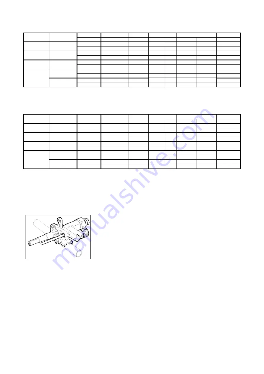
Regulation of burners
Work surface burner adjustment
: follow the instructions below to adjust the work surface burner minimum:
1) Light the burner and set the knob to the MINIMUM position (small flame).
2) Remove the knob of the valve that is press fit on the rod of that valve.
3) The cooker is equipped with safety valves, use a small slotted screwdriver the choke valve located on the valve body
and turn the choke screw to the right or left until the burner flame is adjusted to minimum
4) Make sure that the flame does not go out when switching quickly from the
MAXIMUM to the MINIMUM position.
WARNING: The above-mentioned adjustment should be made only for natural gas, while for operation with
liquid gas the screw must be locked at the end in a clockwise direction. The grill burner always
operates at maximum and therefore no minimum adjustment is required.


