background image


13

USING THE STATIC ELECTRIC GRILL


The electric grill can be combined with the gas or electric oven. 
With a gas oven + electric grill combination, the grill is operated from the oven thermostat knob.  
The electric grill for gas oven cookers has a 2500W rating. 

IMPORTANT: When using the electric grill in electric oven cookers, do not turn the thermostat knob to more 
than 150°C to prevent overheating the oven front; the oven has been designed for closed-door grilling.


Grilling on the rack: 

In this case, the rack should be put at level 1 or 2, placing foods on top of the rack and a drip tray 

below.  Turn on the grill heating element, setting the thermostat to the relative position. 

IMPORTANT NOTE: the oven door must be kept closed when grilling using the static electric grill. 
 
WARNING: during use the appliance gets very hot. Do not touch the heating elements inside the oven. 
WARNING: Accessible parts may become hot when the grill is in use. Children should be kept away. 


USING THE ELECTRIC GRILL WITH FAN 


The electric grill with fan is a special function for optimal grilling, with the oven rack at an intermediate position and the 
drip tray below. 
With gas oven cookers with electric grills, set the thermostat to the grill symbol and the 2+0 change-over switch to the 
position to turn on the 1500W grill heating element and fan motor.  
With cookers with a 9-setting change-over switch, set the 9+0 switch to the relative position and the electric thermostat to 
the temperature required, to turn on the grill heating element and fan motor. 

IMPORTANT: When using the electric grill with fan, do not turn the thermostat knob to not more than 175°C 
(between 150° and 200°C) to prevent overheating the oven front; the oven has been designed for closed-door fan 
grilling.  
 

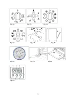
USING THE THERMOMETER Figure 40 

The cooker is fitted with a device to measure the temperature in the middle of the oven. 
This lets you check the temperature inside the oven and adjust food cooking temperatures more accurately. 

ELECTRIC OVEN 

When you turn on the oven, the orange light comes on to indicate that the heating elements are working: The 
thermometer dial will start to move towards the set temperature. 
The orange light will keeping coming on and off, indicating that the heating elements are working to maintain the 
temperature inside the oven. 
The light may go off for a few minutes before the thermometer has reached the temperature required. This is normal, 
because operation of the heating elements is regulated so that heat is distributed properly inside the oven. 
Heat is optimally distributed inside the oven when the thermometer dial has stopped.  
If the oven temperature drops or goes up, the thermometer dial will follow these variations in the same way. 
When the oven is turned off, the temperature on the thermometer will slowly drop until it reaches room temperature. 

NOTE: 

The temperatures on the knob are indicative.  Follow the thermometer temperature for cooking. 

GAS OVEN 

When the oven is turned on, the burner will start working at the maximum and the thermometer dial will start to move 
towards the set temperature.  
The flame may die down  before the thermometer has reached the temperature required. This is because burner power 
is reduced so that heat can be evenly distributed inside the oven.  
Heat is optimally distributed inside the oven when the thermometer dial has stopped.  
When the oven is turned off, the temperature on the thermometer will slowly drop until it reaches room temperature. 

NOTE:

 The Thermostat Position and Oven Temperature correspondence in table no. 6 is indicative and depends on 

various factors such as the type of gas and supply pressure.  
Follow the thermometer temperature for cooking. 

NOTE:

 it is normal to record different temperatures from those indicated on the panel thermometer, when you measure 

the temperature in the middle of the oven using a different thermometer.   
The temperature indicated by the thermometer is the mean temperature inside the oven and does not indicate the 
temperature of any single point. 


3 KEYS ELECTRONIC PROGRAMMER   (fig.43)


The first start up  

The numbers and the A letter on the display are blinking when the oven is switched on for the first time, or 
after a power cut:  
the appliance cannot be operated in this condition

.  

To set the hour and/or to enable the appliance to operate press the M key for at least 2 seconds

the A letter 

turns off and the numbers now are steady on the display.  
The dot (3) starts blinking

press the - or + key to set the hour

.  

The hour is accepted by the programmer just few second after having released the key.  
N.B. the appliance can be correctly used for coking only when you will see on the display the symbol (2). 
  

Summary of Contents for AM64C61BX

Page 1: ...property or to persons caused by incorrect installation or improper use of the appliance The manufacturer is not responsible for any inaccuracies due to printing or transcription errors contained in this booklet In addition the appearance of the figures reported is also purely indicative The manufacturer reserves the right to make changes to its products when considered necessary and useful withou...

Page 2: ...e caused by inappropriate waste handling of this product The symbol on the product indicates that this product may not be treated as household waste Instead it shall be handed over to the applicable collection point for the recycling of electrical and electronic equipment Disposal must be carried out in accordance with local environmental regulations for waste disposal For more detailed informatio...

Page 3: ...ar combustion of gas and on the ventilation of the room Natural air will flow through permanent openings in the walls of the room to be ventilated these openings will be connected with the outside environment and shall have a minimum cross section defined by the current national standards regarding room ventilation see Fig 2 These openings shall be built so that they cannot be clogged Indirect ven...

Page 4: ...he gas type label affixed near the gas connection point If not contact Bertazzoni Service Center for a Gas Conversion Kit Natural Gas The natural gas regulator supplied must be fitted for natural gas Ensure the arrow on the regulator points towards the direction of the gas flow Commissioning Procedure The test point pressure must be adjusted to 1 00 kPa with the Wok and Rapid Burners operating on ...

Page 5: ... Natural 1 00 1 18 7 12 Medium U LPG 2 75 0 70 6 20 Large Natural 1 00 1 55 12 0 Large U LPG 2 75 0 92 11 25 Wok Natural 1 00 1 55 12 5 Wok U LPG 2 75 0 95 13 1 Oven Natural 1 00 1 50 10 8 Oven U LPG 2 75 0 85 9 4 BURNER ADJUSTMENT 1 Primary air adjustment Oven burner adjustment follow the instructions below to adjust the primary air for the over burner 1 Remove the oven bottom 2 Loosen the screw ...

Page 6: ...nd wire to an efficient ground system WARNING If the power cord is replaced the ground wire yellow green connected to the terminal should be longer than the other wires by about 2 cm WARNING If the supply cord is damaged it must be replaced by the manufacturer or its service agent or a similarly qualified person in order to avoid a hazard For New Zealand This cooking range must be connected to the...

Page 7: ...ve screws to be able to pull out and reposition the thermostat bulb To replace the oven bulb just unscrew the protection cap that projects out inside the oven Fig 22 WARNING Ensure the appliance is switched off before replacing the lamp to avoid the possibility of electric shock WARNING The power cord supplied with the appliance is connected to that appliance with a type Y connection in compliance...

Page 8: ...releasing the knob repeat the entire operation Note It is recommended not to try to ignite a burner if the relative flame cap is not in the correct position If the flame does not light after the first attempt wait 5 minutes for the gas to dissipate before attempting to re light the burner Tips for using burners correctly Use suitable pots for each burner see tab 5 and Fig 27 When the liquid is boi...

Page 9: ...ignition only for the models equipped with this device In this case first open the oven door then turn the knob to the maximum temperature setting number 8 Then press the thermostat knob models with ignition trough knob Wait about 10 seconds after the burner has been completely lit and then release the knob Make sure that the burner remains on otherwise repeat the operation As for cookers without ...

Page 10: ...ermostat can operate the oven heating elements only if the switch is in one of the heating element operating modes If the switch is set to 0 the thermostat will not operate the heating elements USING THE 9 SETTING MULTI FUNCTION OVEN SELECTOR The 9 0 setting change over switch for multi function ovens is used to control along with the thermostat the fan motor and heating elements To turn on the el...

Page 11: ...inutes at a temperature of 250 to eliminate smell from the internal seals During normal use select the cooking temperature using the thermostat knob then wait for the orange light to go off before putting foods in The oven has 5 grooves at different heights Figure 31a for fitting racks or trays To prevent getting the oven too dirty meat should be cooked on a tray or rack placed in the tray TABLE 8...

Page 12: ... STEER 170 180 2 65 90 ROAST OX 170 190 2 40 60 ROAST VEAL 160 180 2 65 90 ROAST LAMB 140 160 2 100 130 ROAST BEEF 180 190 2 40 45 ROAST HARE 170 180 2 30 50 ROAST RABBIT 160 170 3 80 100 ROAST TURKEY 160 170 3 160 240 ROAST GOOSE 160 180 3 120 160 ROAST DUCK 170 180 2 100 160 ROAST CHICKEN 180 2 70 90 FISH 160 180 2 3 CAKES AND PASTRIES FRUIT CAKE 180 200 2 40 50 SANDWICH CAKE 200 220 2 40 45 BRI...

Page 13: ...e heating elements are working to maintain the temperature inside the oven The light may go off for a few minutes before the thermometer has reached the temperature required This is normal because operation of the heating elements is regulated so that heat is distributed properly inside the oven Heat is optimally distributed inside the oven when the thermometer dial has stopped If the oven tempera...

Page 14: ...s the programming mode for at least 2 sec the symbol switches on Release and touch again the M key On the display the A symbol starts blinking and the writing dur appears Touch again the M key On the display the writing End appears The last one changes few seconds after with the symbol 0 00 Set the end of cooking time with the keys or maximum available time 10hOOm The selected time is automaticall...

Page 15: ...ng during start up Power On At power on the relay contact is opened The display and AUTO symbol flashes and time of day starts from 0 00 Power on state with flashing daytime remains until time of day is set Setting Time of Day Press PLUS and MINUS button simultaneously At Power On also MODE button is possible Time of day can be set with PLUS or MINUS while the colon between hours and minutes is fl...

Page 16: ...t seek technical assistance immediately Cleaning enamelled parts Clean enamelled parts frequently with soapy water to keep their characteristics unaltered Never use abrasive powders Do not leave acid or alkaline substances vinegar lemon juice salt tomato juice etc on enamelled parts and clean the parts when still warm Cleaning stainless steel parts Clean with soapy water then dry with a soft cloth...

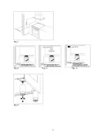
Page 17: ...17 Fig 1 Fig 2 Fig 3 Fig 4 Fig 5 ...

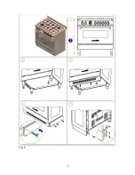
Page 18: ...18 Fig 6 ...

Page 19: ...19 Fig 7 ...

Page 20: ...20 Fig 8 ...

Page 21: ...21 Fig 9 ...

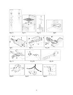
Page 22: ...22 Fig 10 fig 11 fig 12 fig13 fig14 fig15 Fig 16 Fig 17 Fig 18 Fig 19 T Fig 20 fig 21 Fig 22 ...

Page 23: ...23 Fig 23 Fig 24 fig 25 fig 26 fig 27 fig 28 fig 29 fig 30 ...

Page 24: ...24 fig 31a Fig 31b Fig 31c Fig 31d Fig 32 Fig 33 ...

Page 25: ...25 Fig 34 Fig 35 Fig 36 Fig 37 Fig 38 Fig 39 Fig 40 Fig 41 Fig 42 Fig 43 ...

Page 26: ...s must be carried out with the greatest care and attention by authorised personnel For this reason we strongly advise you contact the Bertazzoni Service Center specifying the nature of the problem the model of the equipment and the serial number This data is provided on the data label adhered to the base of the appliance and on the duplicate data label Always use original Bertazzoni spare parts OV...

Page 27: ...X BERTAZZONI GROUP ABN 38 069 686 326 650 Bridge Road Richmond Victoria 3121 Service Spare Parts 1300 748 308 Bertazzoni After Sales Service P O Box 543 SOMERTON VIC 3061 Email customercare bertazzonigroup com au ...

Page 28: ...28 Cod 310793 ...

Reviews: