- 6 -
- 7 -
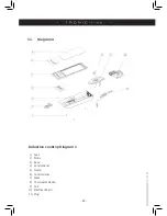
1) Fan
14) Main PCB
15) Filter PCB
16) Coil
17) Sensor
18) Control PCB
19) Control panel
0) Control panel
1) Crew
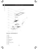
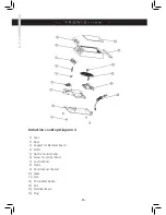
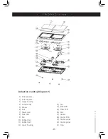
Induction cooktop Diagram 5
1) Ceramic plate
) Ceramic plate
) Upper housing
4) Control PCB
5) Sensor
6) Coil
7) Power cord
8) Main PCB
9) Fan
10) Rubber foot
11) Rubber foot
1) Lower housing


