8
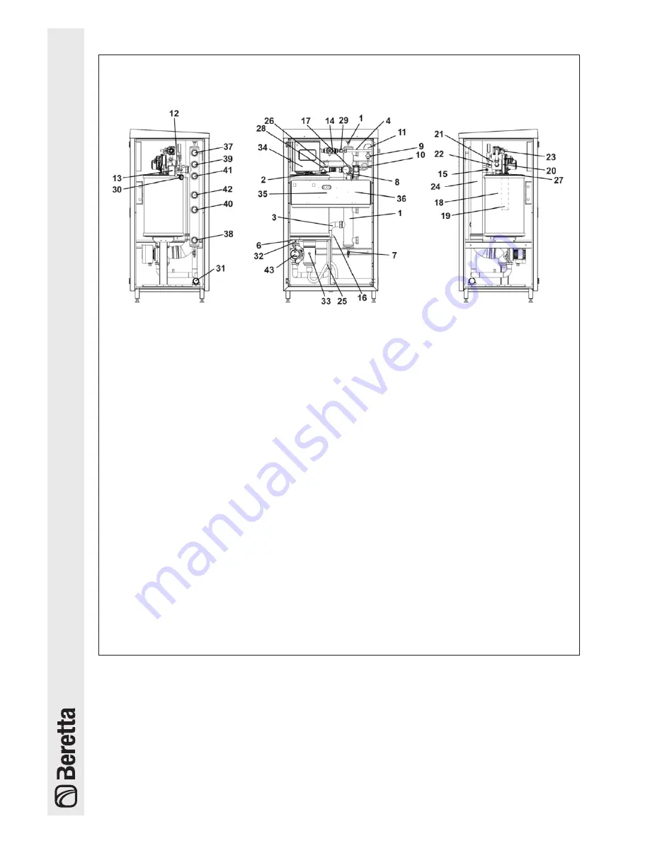
SYSTEM COMPONENTS
Figure 5
1
Hydraulic separator
2
Flow pipe
3
Return pipe
4
Gas pipe
5
Vent valve
6
Cock
7
Drain cock
8
Temperature gauge
9
Gauge fitting with cock
10
Damper device for gauge
11
Pressure gauge
12
Thermometer pit
13
Maximum pressure switch
14
Fuel check valve
15
5.4 bar safety valve
16
Expansion tank/filling fitting
17
Flow probe pit
18
Exchanger
19
Burner
20
Fan
21
Venturi tubes
22
Air inlet pipe
23
Gas valve
24
Exhaust flue duct
25
Condensate drainpipe
26
Vent valve
27
Ignition detection electrode
28
Safety thermostat
29
Gas cock
30
Diff. Pressure switch
31
Condensate drain manifold
32
Return probe
33
Exhaust flue probe
34
Master board
35
Slave board
36
Pump control board
37
Flow hot water system connection
38
Return hot water system connection
39
Flow high temperature connection
40
Return high temperature connection
41
Flow low temperature connection
42
Return low temperature connection
43
Modulating circulator
Summary of Contents for Power Plus Box 1001 EXT
Page 1: ...Installation Manual CONDENSING Power Plus Box 1001 INT EXT Installation Manual EN...
Page 35: ...35 12 WIRING DIAGRAMS...
Page 36: ...36...
Page 39: ...39...


