


Installing the device
28
The control cable must be routed from the wall box
to the connection terminals for the wall box in the
extractor hood.
The connection terminals for the wall box are
marked "BMK" and "Wall box" in the extractor hood.
In order to connect the control cable, the control
cable's two wires must be connected to terminals 1
and 2 for the wall box in the extractor hood. The
wires are numbered. The actuation contact is
potential-free.
•
The wall box is closed when the actuation contact
in the extractor hood is open (see connection
schematic).
•
The wall box is open when the actuation contact
in the extractor hood is closed.
Connection of the BMK-F series wall box is
described in the following section.
For this step, a small standard screwdriver is
required for the connection terminals in the berbel
extractor hood.
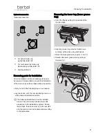
¾
Route the wall box control cable to the extractor
hood.
¾
Make sure that the terminals for the wall box
contact in the extractor hood are accessible.
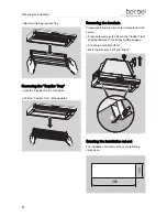
The connection terminals for the multi-function
contact and the wall box contact are located in the
upper corner of the control box. The connection
terminals are marked "Window switch" and "BMK"
or "Wall box". The terminal pairs are labelled "1"
and "2".
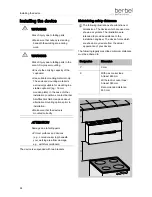
Proceed as follows to connect the control cable:
¾
Unscrew the screw for "BMK" terminal 1.
¾
Take up offset wire 1 of the control cable.
¾
Guide wire 1 into terminal 1.
¾
Make sure that the control cable's wire connector
sleeve is completely in the terminal.
¾
Make sure that the control cable's insulation is not
in the terminal.


