background image

Parts of the display and their functions

11

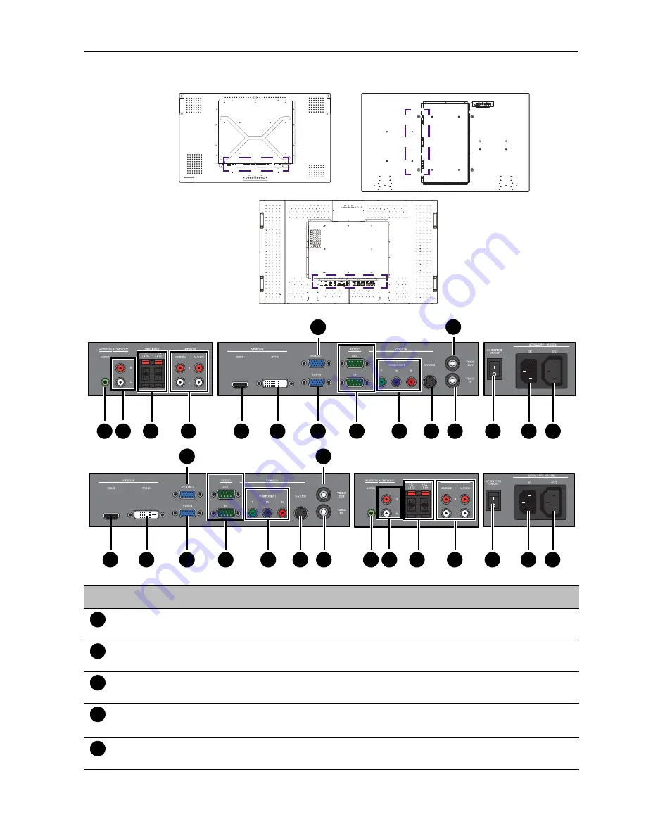
Input/output terminals

T420

TL550

T650

No.

Name

Description

AUDIO IN 
(AUDIO1)

Receives audio signals from an external device (such as a 

computer).

AUDIO OUT (R/L)

Outputs audio signals from an audio or HDMI input source to an 

external device.

SPEAKERS (R/L)


Outputs audio signals from an audio or HDMI input source to 

external speakers.

AUDIO IN

(AUDIO2/AUDIO3)

Receives audio signals from an external device (such as a VCR or 

DVD player).

VIDEO IN (HDMI)

Receives HDMI signals from an external device (such as a Blu-ray 

disc player).

1

5

6

7

11

12

14

15

16

13

8

2

3

4

9

10

T420

TL550 / T650

5

6

7

11

12

14

15

16

13

8

2

3

4

9

10

1

1

2

3

4

5

Summary of Contents for T420

Page 1: ...Interactive Flat Panel User Manual T420 TL550 T650 ...

Page 2: ...contents thereof without obligation to notify any person of such revision or changes Copyright Copyright 2012 BenQ Corporation All rights reserved No part of this publication may be reproduced transmitted transcribed stored in a retrieval system or translated into any language or computer language in any form or by any means electronic mechanical magnetic optical chemical manual or otherwise witho...

Page 3: ...als 11 Remote control 13 Using the remote control 14 Setting up the display 15 Mounting the display 15 Connecting audio video signals 18 Connecting the touch module 25 Connecting power 26 Using the touch screen 27 Calibrating the touch screen 30 Important instructions for using the touch screen 30 Basic operations 31 Turning the display on or off 31 Locking unlocking the controls 31 Switching inpu...

Page 4: ...ion menu 36 Setting menu 38 Product information 40 Specifications 40 Supported input signal resolution 44 Supported PIP input signal combination 45 Supported signal source and resolution in PIP mode 46 Troubleshooting 55 ...

Page 5: ...y Using wrong or unsuitable accessories may cause the display to fall and result in serious personal injuries Make sure that the surface and fixing points are strong enough to sustain the weight of the display To reduce the risk of electric shock do not remove covers No user serviceable parts inside Refer servicing to qualified service personnel To prevent personal injuries mounting the display or...

Page 6: ...rms or when unused for long periods of time 14 Refer all servicing to qualified service personnel Servicing is required when the apparatus has been damaged in any way such as power supply cord or plug is damaged liquid has been spilled or objects have fallen into the apparatus the apparatus has been exposed to rain or moisture does not operate normally or has been dropped Notes on the LCD panel of...

Page 7: ...object between the remote control and the remote sensor of the product When the remote control will not be used for an extended period remove the batteries Battery safety notice The use of the wrong type of batteries may cause chemical leaks or explosion Please note the following Always ensure that the batteries are inserted with the positive and negative terminals in the correct direction as show...

Page 8: ...al accessories are also available separately LCD display Power cord D Sub 15 pin cable Remote control AAA batteries Quick start guide CD USB cable for T650 The type of power cord supplied may differ from that illustrated depending on your region of purchase Before discarding the package check that you haven t left any accessories inside the box Do not leave plastic bags within reach of young child...

Page 9: ...ntrol Detects ambient lighting conditions around the display and adjusts screen brightness automatically when the Ambient Light Sensor function is activated Indicates the operating status of the display Lights up green when the power is turned on Lights up red when the display is turned off Lights up red when the display is in Standby Eco mode Flashes red when the display is in Standby Standard mo...

Page 10: ...a previous menu or exits the OSD menu Scrolls through settings and options in the OSD menu Power button Turns on the display or puts it in standby mode Power indicator Indicates the power status of the display Lights up green when the power is turned on Lights up red when the display is turned off Lights up red when the display is in Standby Eco mode Flashes red when the display is in Standby Stan...

Page 11: ...audio or HDMI input source to an external device SPEAKERS R L Outputs audio signals from an audio or HDMI input source to external speakers AUDIO IN AUDIO2 AUDIO3 Receives audio signals from an external device such as a VCR or DVD player VIDEO IN HDMI Receives HDMI signals from an external device such as a Blu ray disc player 1 5 6 7 11 12 14 15 16 13 8 2 3 4 9 10 T420 TL550 T650 5 6 7 11 12 14 15...

Page 12: ...the RS232C IN input to another display VIDEO IN COMPONENT Receives component video YPbPr signals from an external device such as a DVD player HDTV device or Laser disc player VIDEO IN S VIDEO Receives S Video signals from an external device such as a VCR or DVD player VIDEO IN Receives composite video signals from an external device such as a VCR or DVD player VIDEO OUT Outputs composite video sig...

Page 13: ... Selects the VGA input source DVI Selects the DVI input source Power Turns on the display or puts it in standby mode EXIT Returns to a previous menu or closes the OSD menu ENTER Confirms your selection or save changes VOL Scrolls through settings and options in the OSD menu Turns up the volume Scrolls through settings and options in the OSD menu MENU Opens or closes the OSD menu AV Selects the AV ...

Page 14: ...ht the remote control may not operate properly In this situation change the light source readjust the angle of the display or operate the remote control from a location closer to display s remote control sensor window 1 Open the remote control battery compartment cover 2 Insert the supplied batteries ensuring that the positive and negative marked battery terminals match the and marks in the batter...

Page 15: ... to qualified technicians Improper installation may cause the display to fall or malfunction Installing the display on a wall 1 Place a clean dry and lint free cloth on a flat horizontal and object free surface Make sure that the size of the cloth is larger than the display 2 Gently lay the display on the cloth with the LCD screen facing down 3 Remove the desktop stands from the display if install...

Page 16: ... strong enough to bear the weight of the display To maintain proper ventilation keep at least 10 mm of clear space from the back cover of the display to the wall Please consult a professional technician for wall mount installations The manufacturer accepts no liability for installations not performed by a professional technician 1 Place a clean dry and lint free cloth on a flat horizontal and obje...

Page 17: ...Setting up the display 17 3 Place the desktop stands on the display as illustrated 4 Use the screws and a suitable screwdriver to secure the stands on the display T650 T420 TL550 T420 TL550 T650 ...

Page 18: ...ways grasp and pull the connectors at the end of the cable Ensure that all cables are fully inserted and firmly seated Connecting the VGA input 1 Connect the VGA IN jack on the display to the VGA output jack on a computer using a D Sub 15 pin cable 2 Connect the computer s audio output jack to the AUDIO IN AUDIO1 jack on the display using a suitable audio cable 3 If a second display is used connec...

Page 19: ... images from this input press the VGA button on the remote control The audio cable is not supplied and should be purchased separately First display Second display D Sub 15 pin cable D Sub 15 pin cable Audio cable Computer TL550 T650 T420 ...

Page 20: ...IDEO IN HDMI input jack on the display using an HDMI cable or a DVI D to HDMI conversion cable 2 Connect the computer s audio output jack to the AUDIO IN AUDIO1 jack on the display using a suitable audio cable 3 To view video image from this input press the DVI or HDMI button on the remote control The cables are not supplied and should be purchased separately Audio cable Computer DVI D cable DVI D...

Page 21: ... or DVD player using a component video cable 2 Connect the DVD player s audio output jacks to the AUDIO IN AUDIO2 or AUDIO3 jacks on the display using a suitable audio cable 3 To view video image from this input press the YPbPr button on the remote control The cables are not supplied and should be purchased separately Audio cable DVD player VCR Component video cable TL550 T650 T420 ...

Page 22: ...3 If a second display is used connect the VIDEO OUT jack on the first display to the VIDEO IN jack on the second display using an AV cable This relays the input signal from the first display to the second one 4 To view video image from this input press the AV button on the remote control for the AV signal or press the INPUT button repeatedly for the S Video signal The cables are not supplied and s...

Page 23: ...lt in amplifier on the display allows you to output audio signals through external speakers Connect external speakers to the SPEAKERS R L jacks on the display You can use the remote control or the control panel on the display to adjust the volume External speakers ...

Page 24: ...displays serially daisy chain to a computer for management The number of displays you can connect serially depends on the resolution of the input signal you use This function requires an RS 232C port equipped computer with the display management software installed RS 232C cable RS 232C cable RS 232C cable Computer ...

Page 25: ...lay 25 Connecting the touch module Connect the USB cable on the display to a computer The touch module supports easy Plug and Play operations There is no need to install additional drivers on the computer TL550 T420 T650 ...

Page 26: ...or use with 110 240V AC power only The power cord and outlet illustrated may differ from the ones used in your region Only use an appropriate power cord for your region Never use a power cord which appears damaged or frayed or change the plug type on the power cord Be aware of the power loading when you use extension cords or multiple outlet power boards There are no user serviceable parts in this...

Page 27: ... touch functions are only supported by Windows 7 Home Premium Professional Enterprise and Ultimate versions For Windows XP Windows Vista and Windows 7 Starter and Home Basic versions multi touch is not supported Windows is a registered trademark of Microsoft Corporation in the United States and other countries OS functions Gesture actions For Windows XP Windows Vista and Windows 7 Click Tap the sc...

Page 28: ...er Flick in a desired direction Multi touch functions For Windows 7 Home Premium Professional Enterprise and Ultimate versions Right click 1 Press on the target 2 Tap the screen with another finger 3 Release the second finger Scrolling Drag one or two fingers up or down Zoom Move two fingers apart or toward each other OS functions Gesture actions or ...

Page 29: ...ions Use one finger to pivot around another Supported by specific applications Tap two fingers simultaneously The target should be the midpoint between the fingers For Windows XP Windows Vista and Windows 7 Wakeup from Windows sleep mode S3 Press and hold for 4 seconds OS functions Gesture actions ...

Page 30: ...en cannot function normally if the bars are bent Keep the touch screen out of direct sunlight or spotlights Avoid displaying still images to prevent image retention Regularly clean the retro reflective bars with a clean soft cloth A dusty environment may adversely affect the performance of your touch screen Clean the retro reflective bars as illustrated below Do not clean the touch sensors on the ...

Page 31: ...d MENU and for 5 seconds Once locked the display does not respond to any remote control operations unless unlocked Switching input signals Press the INPUT button on the remote control or the INPUT button on the control panel to select an input signal Adjusting audio volume level Press on the control panel or VOL VOL on the remote control to adjust the volume To turn on or off the display press the...

Page 32: ...Input Resolution 34 Sound Volume Mute Audio Source Speaker 35 Option Aspect ratio PIP Video Source Auto Adjustment Clock Frequency Phase H Position V Position Ambient Light Sensor Auto Detection Touch Feature 36 Setting Language Overscan Schedule Display Wall Power Save Set Monitor ID Image Retention Auto Adjustment Advanced 38 Some options are only available when a certain input signal source is ...

Page 33: ... Press ENTER VIDEO SOURCE to confirm selections 3 Press ENTER to confirm selections 4 Press or to select a feature and press or to adjust settings Press ENTER VIDEO SOURCE to save changes 4 Press and to select a feature and press or to adjust settings Press ENTER to confirm changes 5 Press MENU to close the OSD menu 5 Press EXIT to close the OSD menu ENTER VIDEO SOURCE ENTER VIDEO SOURCE ENTER VID...

Page 34: ...n Picture Mode is set to User Tint Adjusts the color tint when Picture Mode is set to User Sharpness Adjusts the image sharpness when Picture Mode is set to User Backlight Adjusts the backlight intensity for the screen This feature is not available if the Ambient Light Sensor function is set to HIGH or LOW DCR Turns the DCR function on or off This feature enhances image contrast for dark scenes Th...

Page 35: ...ource Sets the audio input source Speaker Sets the audio source External Selects the audio output source from SPEAKERS R L on the rear connector panel Line Out Selects the audio output source from AUDIO OUT R L on the rear connector panel Internal Select the audio input source from AUDIO IN on the rear connector panel This is an optional feature and may not be available for all models Audio 2 Audi...

Page 36: ...tion Changes the position of the sub picture This feature is not available for AV and S Video inputs PIP is not available for all signal source combinations See Supported PIP input signal combination on page 45 for more information on supported combinations In PIP mode only sounds from the Main Input picture will be available Video Source Sets the video input source Auto Adjustment Automatically o...

Page 37: ...tion V Position Overscan and Display Wall will be disabled to optimize touch performance This feature is only available for VGA DVI and HDMI inputs The adjustment of the Clock Frequency Phase H Position and V Position settings is only required when the Auto Adjustment function does not work perfectly on certain input signals ...

Page 38: ...urce should be used for each schedule Set the current time before you set the Schedule When schedule settings overlap the Every Day setting takes priority over other weekly settings When schedule settings overlap scheduled power on time takes priority over scheduled power off time If two schedules have the same settings the first schedule on the list will take priority Display Wall H Monitors V Mo...

Page 39: ...ally displays swift moving patterns every 10 seconds to prevent image retention on the screen Auto Adjustment Automatically optimizes image display for the VGA input Advanced Reset User Default Resets all OSD settings except the Language setting to the factory settings OSD Info Box When turned ON the display will always show the current input source and resolution onscreen Select OFF to show the i...

Page 40: ...e area Touch Output USB 2 0 PC Support Windows XP Vista 7 Glass Tempered glass 3 8 mm 0 mm 0 3 mm 5 mm 0 mm 0 3 mm Input Computer VGA D Sub 15 pin DVI DVI D Video Composite Video BNC jacks S Video YPbPr RCA jacks HDMI Audio L R RCA jacks Line in 3 5 mm Mini jack Control RS 232C Mini D Sub 9 pin Output Computer VGA D Sub 15 pin Video Composite Video BNC jacks Speaker External speaker jack 12W 12W 8...

Page 41: ...uct information 41 Mechanical Weight kg 30 5 Approximately 45 0 Approximately Dimensions W x H x D mm 992 x 585 x 128 9 1263 2 x 744 2 x 95 Specifications and functions are subject to change without notice ...

Page 42: ... Vista 7 Glass Tempered glass 5 mm 0 mm 0 3 mm Input Computer VGA D Sub 15 pin DVI DVI D Video Composite Video BNC jacks S Video YPbPr RCA jacks HDMI Audio L R RCA jacks Line in 3 5 mm Mini jack Control RS 232C Mini D Sub 9 pin Output Computer VGA D Sub 15 pin Video Composite Video BNC jacks Speaker External speaker jack 12W 12W 8 Ohms Audio L R RCA jacks Control RS 232C Mini D Sub 9 pin Audio Aud...

Page 43: ...Product information 43 Mechanical Weight kg 71 Approximately Dimensions W x H x D mm 1522 2 x 889 2 x 145 8 ...

Page 44: ... 640 x 480 75Hz 720 x 400 70Hz 800 x 600 60Hz 800 x 600 75Hz 1024 x 768 60Hz 1024 x 768 75Hz 1280 x 768 60Hz 1280 x 960 60Hz 1280 x 1024 60Hz 1360 x 768 60Hz 1366 x 768 60Hz 1600 x 1200 60Hz 1920 x 1080 60Hz 576i 50Hz 480i 60Hz 480p 60Hz 576p 50Hz 720p 50Hz 720p 60Hz 1080i 50Hz 1080i 60Hz 1080p 50Hz 1080p 60Hz supported Blank not supported ...

Page 45: ...Product information 45 Supported PIP input signal combination Main picture signal source AV S Video VGA YPbPr DVI HDMI Sub picture signal source AV S Video VGA YPbPr DVI HDMI ...

Page 46: ...00 60Hz 800 x 600 75Hz 1024 x 768 60Hz 1024 x 768 75Hz 1280 x 768 60Hz 1280 x 960 60Hz 1280 x 1024 60Hz 1360 x 768 60Hz 1366 x 768 60Hz 1600 x 1200 60Hz 1920 x 1080 60Hz 640 x 480 60Hz 640 x 480 72Hz 640 x 480 75Hz 720 x 400 70Hz 800 x 600 60Hz 800 x 600 75Hz 1024 x 768 60Hz 1024 x 768 75Hz 1280 x 768 60Hz 1280 x 960 60Hz 1280 x 1024 60Hz 1360 x 768 60Hz 1366 x 768 60Hz 1600 x 1200 60Hz 1920 x 108...

Page 47: ...24 x 768 75Hz 1280 x 768 60Hz 1280 x 960 60Hz 1280 x 1024 60Hz 1360 x 768 60Hz 1366 x 768 60Hz 1600 x 1200 60Hz 1920 x 1080 60Hz 640 x 480 60Hz 640 x 480 72Hz 640 x 480 75Hz 720 x 400 70Hz 800 x 600 60Hz 800 x 600 75Hz 1024 x 768 60Hz 1024 x 768 75Hz 1280 x 768 60Hz 1280 x 960 60Hz 1280 x 1024 60Hz 1360 x 768 60Hz 1366 x 768 60Hz 1600 x 1200 60Hz 1920 x 1080 60Hz ...

Page 48: ...5Hz 720 x 400 70Hz 800 x 600 60Hz 800 x 600 75Hz 1024 x 768 60Hz 1024 x 768 75Hz 1280 x 768 60Hz 1280 x 960 60Hz 1280 x 1024 60Hz 1360 x 768 60Hz 1366 x 768 60Hz 1600 x 1200 60Hz 1920 x 1080 60Hz 1080p 60Hz 1080p 50Hz 1080i 60Hz 1080i 50Hz 720p 60Hz 720p 50Hz 576p 50Hz 480p 60Hz 480i 60Hz 576i 50Hz ...

Page 49: ...024 x 768 75Hz 1280 x 768 60Hz 1280 x 960 60Hz 1280 x 1024 60Hz 1360 x 768 60Hz 1366 x 768 60Hz 1600 x 1200 60Hz 1920 x 1080 60Hz 640 x 480 60Hz 640 x 480 72Hz 640 x 480 75Hz 720 x 400 70Hz 800 x 600 60Hz 800 x 600 75Hz 1024 x 768 60Hz 1024 x 768 75Hz 1280 x 768 60Hz 1280 x 960 60Hz 1280 x 1024 60Hz 1360 x 768 60Hz 1366 x 768 60Hz 1600 x 1200 60Hz 1920 x 1080 60Hz ...

Page 50: ... 60Hz 1280 x 960 60Hz 1280 x 1024 60Hz 1360 x 768 60Hz 1366 x 768 60Hz 1600 x 1200 60Hz 1920 x 1080 60Hz 576i 50Hz 480i 60Hz 480p 60Hz 576p 50Hz 720p 50Hz 640 x 480 60Hz 640 x 480 72Hz 640 x 480 75Hz 720 x 400 70Hz 800 x 600 60Hz 800 x 600 75Hz 1024 x 768 60Hz 1024 x 768 75Hz 1280 x 768 60Hz 1280 x 960 60Hz 1280 x 1024 60Hz 1360 x 768 60Hz 1366 x 768 60Hz 1600 x 1200 60Hz 1920 x 1080 60Hz ...

Page 51: ... 50Hz 1080i 60Hz 1080p 50Hz 1080p 60Hz 640 x 480 60Hz 640 x 480 72Hz 640 x 480 75Hz 720 x 400 70Hz 800 x 600 60Hz 800 x 600 75Hz 1024 x 768 60Hz 1024 x 768 75Hz 1280 x 768 60Hz 1280 x 960 60Hz 1280 x 1024 60Hz 1360 x 768 60Hz 1366 x 768 60Hz 1600 x 1200 60Hz 1920 x 1080 60Hz ...

Page 52: ...720p 50Hz 720p 60Hz 1080i 50Hz 1080i 60Hz 1080p 50Hz 1080p 60Hz 640 x 480 60Hz 640 x 480 72Hz 640 x 480 75Hz 720 x 400 70Hz 800 x 600 60Hz 800 x 600 75Hz 1024 x 768 60Hz 1024 x 768 75Hz 1280 x 768 60Hz 1280 x 960 60Hz 1280 x 1024 60Hz 1360 x 768 60Hz 1366 x 768 60Hz 1600 x 1200 60Hz 1920 x 1080 60Hz ...

Page 53: ...75Hz 720 x 400 70Hz 800 x 600 60Hz 800 x 600 75Hz 1024 x 768 60Hz 1024 x 768 75Hz 1280 x 768 60Hz 1280 x 960 60Hz 1280 x 1024 60Hz 1360 x 768 60Hz 1366 x 768 60Hz 1600 x 1200 60Hz 1920 x 1080 60Hz 1080p 60Hz 1080p 50Hz 1080i 60Hz 1080i 50Hz 720p 60Hz 720p 50Hz 576p 50Hz 480p 60Hz 480i 60Hz 576i 50Hz ...

Page 54: ...ure HDMI Sub picture YPbPr 576i 50Hz 480i 60Hz 480p 60Hz 576p 50Hz 720p 50Hz 720p 60Hz 1080i 50Hz 1080i 60Hz 1080p 50Hz 1080p 60Hz 1080p 60Hz 1080p 50Hz 1080i 60Hz 1080i 50Hz 720p 60Hz 720p 50Hz 576p 50Hz 480p 60Hz 480i 60Hz 576i 50Hz ...

Page 55: ...k the following Have you turned on the mute function on the display or the input source device Turn off the mute function or increase the audio volume level and try again Are there any loose cable connections Make sure that all cables are connected firmly The computer input image looks strange Have you chosen an unsupported output resolution on the computer Refer to Supported input signal resoluti...

Page 56: ...ointed at the display s remote control sensor window Check for any obstacle between the remote control and the remote control sensor window Check that the remote control sensor window is not under strong fluorescent lighting or in direct sunlight Check for any devices computer or personal digital assistant PDA nearby that transmit infrared signals which may cause interference to signal transmissio...

Reviews: