


16
17
• To restore the automatic movement of the bar, turn the key in an anti-clockwise direction until it is blocked.
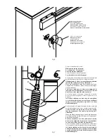
7. Balancing (fig. 7)
For good operation of the barrier it is fundamental for the bar to be suitably balanced by the action of the spring.
To check this, proceed as follows:
• Ensure that the spring is fixed to the correct point of the lever (see paragraph 2).
• Mechanically release the barrier using the release key.
• The correctly balanced bar must stay still in whichever point it is positioned:
- if it tends to open, decrease the tension of the spring
- if it tends to close, increase the tension of the spring
The tension of the spring may be regulated by manually screwing (anti-clockwise rotation) or unscrewing
(clockwise rotation) the spring itself. Once you have regulated the spring tension, block it, screwing down
the nut “D” until it makes contact with the cap T.
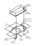
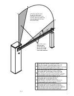
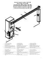
8. Movements and work times (fig. 8)
During the closing manoeuvre:
The bar starts from point “A” and arrives at the point “C” of intervention of the slowing limit stop with a speed
that may be set by the control unit.
The braking cycle starts from the intervention of the slowing limit stop and concludes exclusively with the in-
tervention of the closing limit stop in point “D”, since the control unit checks when the limit stop “D” is reached
and is able to compensate automatically any variations due, for example, to different climatic conditions. The
braking angle is fixed and corresponds to about 25°.
During the opening manoeuvre:
The bar starts from point “D” and arrives at the point “B” of intervention of the opening limit stop with a speed
that may be set by the central control unit.
The bar covers the braking space when opening in a time defined by the control unit.
The bar then arrives at point A, completing the opening movement.
The regulations of the limit stop cams, of the trimmers and of the dip-switches must be carried out referring to
these operating principles.
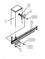
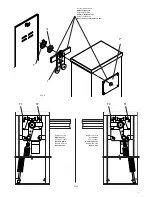
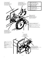
9. Regulating the limit stop cams
The regulation of the limit stop cams allows:
Cam A
Anticipate or delay the start of the slowing phase in opening (Fig.8- point “B”).
Cam C
Regulate with precision the stopping point in closing (Fig.8 - point “D”).
Note: Before activating the closing limit stop (Fig.9 - D), the cam C starts the slowing phase, activating the
slowing limit stop (Fig.9 - C).
With reference to Fig.9:
• Slacken the cam fixing screw V.
• Bring the opening or closing cam into the desired position.
• Tighten the cam fixing screw V.
10. Regulating the mechanical stops
The inertial movement of the bar after the motor stops is blocked using the adjustable mechanical stops shown
in Fig.10.
After having regulated the opening/closing limit stop cam, bring the respective closing mechanical stop into
contact with the lever. The opening mechanical stop is of the damped type.
With reference to Fig.10:
• Slacken the blocking dowel
• Tighten /unscrew the mechanical stop until the desired position of intervention is obtained
• Tighten the blocking dowel
ATTENTION
The third-party liability policy on the products, which covers any damage to persons or things caused by manu-
facturing defects, requires that the system comply with the regulations in force and that authentic Benincà ac-
cessories be used.


