background image

3

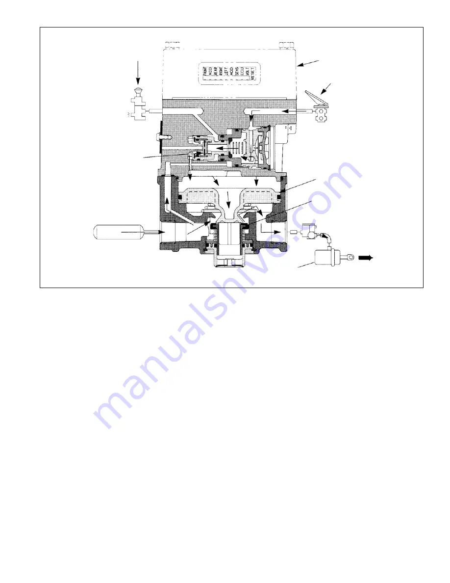
FIGURE 3 - TRACTOR SERVICE BRAKES APPLYING - TRACTOR TRAILER COMBINATION

SERVICE BRAKES APPLYING - TRACTOR/TRAILER
COMBINATION

Brake application air enters the AR-2

 valve service port

and is conducted through the service piston then through
the center of both the blend back and proportioning pistons
to the inlet and exhaust valve. Flowing around the inlet valve,
application air moves through a passage in the cover to the
top of the service relay piston. In response to air pressure,
the relay piston moves into contact with the exhaust portion
of its inlet and exhaust valve. With the exhaust passage
sealed, continued movement of the piston unseats the inlet
portion of the inlet and exhaust valve, allowing supply air
from the reservoir to flow out the AR-2

 valve delivery ports

to the brake chambers.

SERVICE BRAKES HOLDING - TRACTOR/TRAILER
COMBINATION

The air pressure being delivered to the brake chambers is
also present beneath the relay piston.
When the air pressure above and below relay piston is
equal, the piston moves slightly allowing the inlet valve to
return to its seat. The exhaust valve remains closed. With
both the inlet and exhaust valves closed, air pressure in the
brake chambers is held stable and neither increases nor
decreases.

SERVICE BRAKES RELEASING - TRACTOR/TRAILER
COMBINATION

When the brake application is released, air from above the
relay piston, flows back through the proportioning, blend
back and service pistons to the foot brake valve and is
exhausted. As air pressure is reduced above the relay
piston, pressure beneath it lifts the piston away from the
exhaust valve and opens the exhaust passage. Air from the
service brake chambers returns to the AR-2

 valve and flows

out the open exhaust.

SERVICE APPLICATION - BOBTAIL TRACTOR

When the trailer supply valve (dash control with red octagonal
button) is activated to disconnect the trailer, air in the AR-2

valve control port and trailer supply line is exhausted to
atmosphere. During bobtail tractor operation, service
application air enters the AR-2

 valve service port and as it

passes through the blend back piston air exerts a force on
the full effective diameter of the piston. The blend back piston
remains stationary at application pressures below
approximately 80 psi because of opposing reservoir air
acting on the large diameter. Application air flowing through
the blend back piston also exerts a force on the small
diameter of the proportioning piston while simultaneously

TRAILER

SUPPLY

VALVE

INLET-OPEN

EXHAUST-CLOSED

REAR AXLE

SERVICE

CHAMBER

RELAY PISTON

SERVICE

BRAKE

VALVE

ANTILOCK

CONTROLLER

INLET-OPEN

EXHAUST-CLOSED

M-21

 MODULATOR

Summary of Contents for AR-2 ANTILOCK RELAY VALVE

Page 1: ...he standard relay valve used to control the rear axle service brakes and performs the standard relay function during tractor trailer operation During tractor bobtail operation theAR 2 valve reduces brake application pressure to the lighter rear axle s brakes to improve vehicle controllability and minimize rear axle s wheel skid before antilock is required TheAR 2 valve provides added vehicle braki...

Page 2: ...5 covering the EC 15 electronic controller Other useful information regarding antilock system components used in conjunction with the AR 2 valve is contained in publications SD 13 4793 covering the M 21 antilock modulator and SD 13 4754 covering the WS 20 wheel speed sensor INITIAL CHARGING During the initial build up of tractor system air pressure reservoir air flows into the supply port and thro...

Page 3: ... and neither increases nor decreases SERVICE BRAKES RELEASING TRACTOR TRAILER COMBINATION When the brake application is released air from above the relay piston flows back through the proportioning blend back and service pistons to the foot brake valve and is exhausted As air pressure is reduced above the relay piston pressure beneath it lifts the piston away from the exhaust valve and opens the e...

Page 4: ...ning will occur for all service applications between approximately 30 and 80 psi Service applications of more than 80 psi cause the blend back piston to begin to move Service air pressure acting on the full diameter of the blend back piston over comes the resistance of reservoir pressure acting on the large diameter of the other side Above 80 psi the ratio between control and delivered air pressur...

Page 5: ... damage Replace as necessary 3 Test air line fittings for excessive leakage and tighten or replace as necessary 4 Perform the Leakage Test described in this manual EVERY YEAR 100 000 MILES OR 3 600 OPERATING HOURS 1 Perform the Operation and Leakage Tests described in this manual WARNING PLEASE READ AND FOLLOW THESE INSTRUCTIONS TO AVOID PERSONAL INJURY OR DEATH When working on or around a vehicle...

Page 6: ...TOR TRAILER SUPPLY VALVE INLET CLOSED EXHAUST CLOSED REARAXLESERVICE CHAMBER SERVICE BRAKE VALVE ANTILOCK CONTROLLER INLET CLOSED EXHAUST CLOSED M 21 MODULATOR BLENDBACK PISTON PROPORTIONING PISTON RELAYPISTON TRAILER SUPPLY VALVE REARAXLESERVICE CHAMBER SERVICE BRAKE VALVE ANTILOCK CONTROLLER M 21 MODULATOR ...

Page 7: ...red octagonal button and system park control dash control w yellow diamond button activated for tractor trailer operation apply and release the brakes several times and check for prompt application and release at each wheel If prompt reaction is noted at some but not all wheels test the M 21 antilock modulator between the AR 2 valve and the brake chamber for proper operation If a sluggish response...

Page 8: ...where it joins the body The leakage noted should not exceed a 1 bubble in less than 3 seconds at any exhaust port with no leakage detected between the cover and body VALVE REMOVAL 1 Park the vehicle on a level surface and block the wheels and or hold the vehicle by means other than the air brakes 2 Drain the air pressure from all vehicle reservoirs 3 Identify mark or label all air lines and wiring...

Page 9: ...9 FIGURE 10 AR 2 ANTILOCK RELAY VALVE 1 2 3 30 32 34 36 35 33 31 7 6 5 29 27 25 24 26 28 4 19 17 40 18 39 38 37 8 20 22 21 23 15 13 11 14 12 10 16 9 ...

Page 10: ...e the service piston 23 from the cover 4 13 Remove the spring 24 and spring cage 25 from the cover 4 14 Remove the blend back piston 26 from the valve cover 4 then remove both o rings 27 28 15 Remove the proportioning piston 30 from the valve cover 4 then remove both o rings 29 31 16 While holding the inlet valve seat 34 in place remove the retaining ring 36 from the proportioning piston 30 17 Rem...

Page 11: ...iner 15 surrounds the rubber portion of the valve Install the inlet and exhaust valve in the body 9 17 Install the inlet and exhaust valve return spring 14 in the body 9 18 Install the large and small diameter o rings 13 12 in the cover 11 then install the exhaust cover in the body 9 taking care not to damage the o rings Hold the exhaust cover in place 19 While depressing the exhaust cover 11 inst...

Page 12: ...12 BW1672 2004 Bendix Commercial Vehicle Systems LLC All rights reserved 6 2004 Printed in U S A ...

Reviews: