


3
BP210006 / 12.2007
MLS470, MLS473, MLS474
3.
Die Meldeleitungen 05 und 06
– mit 05 und 06 kennzeichnen
– und abklemmen.
4.
Leistungsleitungen
– mit Leitung 1 und 2 kennzeichnen
– und abklemmen.
5.
Die MLS49x ausbauen.
Bei Umschalteinrichtung mit Klappfenster:
MLS47x sind etwas höher als MLS49x. Den benötigten Platz
schaffen Sie wie folgt:
– Hutschiene 35x15 austauschen gegen Hutschiene
35x7,5
– oder den Abstand des Klappfensters von der Abde-
ckung um 2...5 mm erhöhen.
Neue MLS47x einbauen und anschließen:
1.
Motorantrieb anschließen:
2.
Meldeleitungen anschließen:
3.
Leistungsleitungen 1 und 2 anschließen.
Abschließende Arbeiten und Prüfung
1.
Alle Anschlüsse anhand des Stromlaufplans noch einmal
überprüfen.
2.
Kabelbaum zusammenbinden.
3.
Funktion der Umschalteinrichtung UM107E... gemäß den
Vorgaben in der zugehörigen Bedienungsanleitung über-
prüfen.
Technische Daten
Motorantrieb
Bemessungsspannung U
S
.................................................................................................. AC 230 V
Mindestspannung.................................................................................................................... 207 V
Einschaltimpulsdauer ...............................................................................................................50 ms
Ausschaltimpulsdauer..............................................................................................................50 ms
Dauer des Einschaltvorgangs ............................................................................................. <500 ms
Dauer des Ausschaltvorgangs ............................................................................................ <200 ms
Elektrische Schaltlebensdauer.................................................................................................10 000
Anschluss flexibler/massiver Leiter, min./max. ......................................... 0,75...2,5 / 1...2,5 mm
2
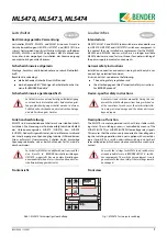
Kennzeichnung an den
Leitungen
Kennzeichnung am MLS47x
L
L
N
N
L
O
O
L
I
I
Kennzeichnung an den
Leitungen
Kennzeichnung am MLS47x
05
11
06
12
95
95 (21)
96
96 (22)
98
98 (24)
3.
Signalling lines 05 and 06
– Label with 05 and 06
– Disconnect
4.
Power lines
– Label as line 1 and 2
– Disconnect
5.
Remove the MLS49x
Switchover equipment with swing-up transparent cover:
MLS47x are a slightly higher than MLS49x. You can create the
space required as follows:
– Replace DIN rail 35x15 by DIN rail 35x7.5
– or increase the distance between the swing-up transpa-
rent window and the cover of the switchover module
by 2...5 mm.
Install and connect the new MLS47x:
1.
Connect the motor drive:
2.
Connect the signalling lines:
3.
Connect the power lines 1 and 2.
Final steps and test
1.
Check all connections against the circuit diagram once
again.
2.
Tie the cable harness together.
3.
Check the function of the UM107E... switchover equip-
ment on the basis of the associated operating manual.
Technical data
Motor drive
Rated voltage U
S
................................................................................................................. AC 230 V
Minimum voltage..................................................................................................................... 207 V
On-pulse duration .................................................................................................................... 50 ms
Off-pulse duration .................................................................................................................... 50 ms
Opening operation...............................................................................................................<500 ms
Closing operation.................................................................................................................<200 ms
Electrical service life, number of cycles...................................................................................10 000
Connection flexible/massive conductors, min./max.................................. 0.75...2.5 / 1...2.5 mm
2
Labelling of the conductors
Labelling of the MLS47x
L
L
N
N
L
O
O
L
I
I
Labelling of the conductors
Labelling of the MLS47x
05
11
06
12
95
95 (21)
96
96 (22)
98
98 (24)


