


2
BP210006 / 12.2007
MLS470, MLS473, MLS474
Installation and connection
Mounting
The device is suitable for snap-on mounting on DIN rails conform-
ing to IEC 60715:1995-10.
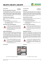
Outline drawing
Fig. 2: MLS470, MLS473 and MLS474 dimensions
MLS49x -> MLS47x replacement
Follow the steps below to install the MLS47x in existing UM107E
switchover equipment:
Preparatory steps:
1.
Remove cable ties on the cable harness around the
MLS49x.
2.
MLS47x devices are 9 mm (0.5 SU) wider than MLS49x (SU
= space unit, to DIN 43880, dimensions 150 x 18 mm). You
can create the space required as follows (only necessary
for UM107E…):
Remove STW2 measuring current transformer from DIN
rails and attach to the side of the rack.
Disconnecting and removing the existing MLS49x:
1.
Control cables:
– Label with L, N, L0, LI
– Disconnect from motor connections
– Place in the lower cable harness
– Lengthen cables if necessary
2.
Signalling lines 95, 96 und 98:
– Label with 95, 96 und 98
– Disconnect
– Place in the upper cable harness
– Lengthen cables if necessary
Before fitting the device and working on the device con-
nections, make sure that no voltage is present. Failure to
comply with this requirement will expose personnel to
the risk of electric shock. Furthermore, the electrical in-
stallation may sustain damage and the device be de-
stroyed beyond repair.
Montage und Anschluss
Montage
Das Gerät ist für Schnellmontage auf Hutprofilschiene nach IEC
60715:1995-10 geeignet.
Maßbild
Abb. 2: Maße MLS470, MLS473 und MLS474
MLS49x -> MLS47x Austausch
Führen Sie die folgenden Schritte aus um MLS47x in eine beste-
hende Umschalteinrichtung UM107E einzubauen:
Vorbereitende Arbeiten:
1.
Kabelbinder am Kabelbaum im Bereich der MLS49x entfer-
nen.
2.
MLS47x sind je 9 mm (0,5 PLE) breiter als MLS49x (PLE =
Platzeinheit, nach DIN 43880, Abmessungen 150 x 18 mm).
Den benötigten Platz schaffen Sie wie folgt (nur bei
UM107E... erforderlich):
Messstromwandler STW2 von Hutschiene lösen und auf
der Seite des Baugruppenträgers befestigen.
Bestehende MLS49x abklemmen und ausbauen:
1.
Steuerleitungen
– mit L, N, L
0
, L
I
kennzeichnen,
– von den Motorantrieben abklemmen
– und in den unteren Kabelbaum verlegen.
– Leitungen, falls erforderlich, verlängern.
2.
Meldeleitungen 95, 96 und 98
– mit 95, 96 und 98 kennzeichnen,
– abklemmen,
– und in den oberen Kabelbaum verlegen.
– Leitungen, falls erforderlich, verlängern.
Stellen Sie vor Einbau des Gerätes und vor Arbeiten
an den Anschlüssen des Gerätes sicher, dass die An-
lage spannungsfrei ist. Wird dies nicht beachtet, so
besteht für das Personal die Gefahr eines elektrischen
Schlages. Außerdem drohen Sachschäden an der ele-
ktrischen Anlage und die Zerstörung des Gerätes.
45
90
99
117
135
MLS470
MLS474
MLS473
44
75
6


