


isoPV1685xxx_D00007_05_M_XXEN/02.2020
22
Device communication
8. Device communication
8.1 RS-485 interface with BMS and Modbus RTU protocol
The RS-485 interface, galvanically isolated from the device electronics, serves as a physi-
cal transmission medium for the BMS and the Modbus RTU protocol. When an
isoPV1685... or other bus devices are interconnected via the RS-485 interface in a net-
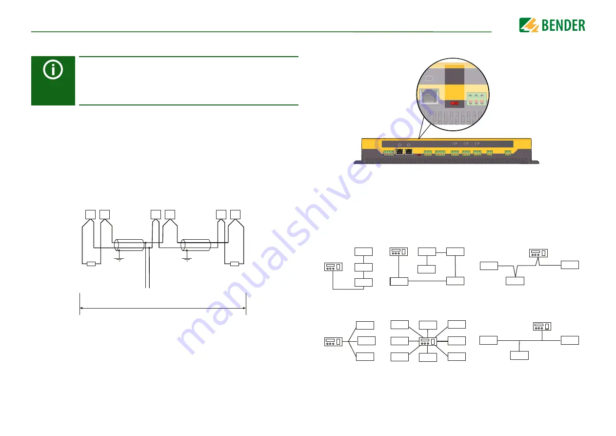
work, the bus must be terminated at both ends with a 120 Ω resistor. For this purpose, the
device is equipped with the terminating switch RS-485 Term.
An RS-485 network that is not terminated is likely to become unstable and may result in
malfunctions. Only the first and last device in one line may be terminated. Hence, stub
feeders in the network must not be terminated. The length of the stub feeders is restrict-
ed to a maximum of 1 m.
The isoPV1685P uses the RS-485 interface for the BMS bus. The
isoPV1685RTU uses the RS-485 interface for the BMS bus or for Modbus
RTU - the device can be switched between BMS and Modbus. Whenever
the RS-485 interface is mentioned in this manual, it refers to the respective
available or configured function (BMS or Modbus) in the device.
A
B
A
B
A
B
1. Gerät
... Gerät
letztes Gerät
120
W
0,6 W
120
W
0,6 W
Stichleitung
max. 1 m
maximale Länge des RS485-Netzwerks: 1200 m
Wiring and termination of the BMS bus
8.1.1 Topology RS-485 network
The optimum topology for an RS-485 network is a daisy-chain connection. In this connec-
tion, device 1 is connected to device 2, device 2 to device 3, device 3 to device n etc. The
RS-485 network represents a continuous path without branches.
Correct arrangement
Three examples for correct arrangement:
Wrong arrangement
Three examples for wrong arrangement:
A1 A2
E KE
21 22 24
31 32 34
k l kT IT
A B S
RS-485
Term.
off on
CAN 1
CAN 2
I2+ I2- I1+ I1-
K3
K2
11 12 14
K1
I2+ I2- I1+ I1-
A B S
k I kT IT
31 32 34
21 22 24
11 12 14
E KE
A1 A2
A B S
RS-485
Term.
off on
CAN 2
A B S
A B S
CAN 2
A B S