Concealed Alert Indicator
Gray Shrink
1
Determine the best location for the Alert
Indicator. If installed by a professional, the customer
should be consulted. An optimal location is clearly
visible from the driver’s position and does not take a
driver’s eyes off the road for more than a moment.
2
Ensure there are no hidden cables, brackets, or
other components behind the mounting location,
and that there is adequate clearance behind the
panel.
3
Cover the mounting surface with masking tape
to prevent accidental scratches.
4
Carefully mark the location and drill a 1/4" hole
through the mounting panel.
5
Remove the masking tape protecting the trim
panel.
6
From the front side, snap one of the panel bezels
provided into the hole.
7
Snap the Alert Indicator into the panel bezel from
the back side.
8
Route the cable to the Interface and plug into the
connector labeled “Concealed Alert LED.”
9
Secure and conceal the cable under trim panels.
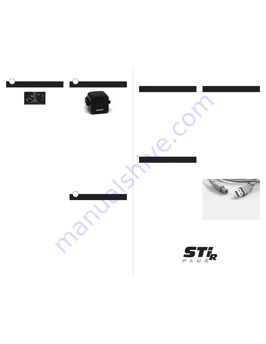
Powered Speaker
1
Determine the best location for the Speaker. It is
loud enough to be mounted behind the dash or
console, under the dash, or under a seat.
2
Using either the supplied hook & loop fastener or
the bracket and hardware, mount the Speaker. If
using the hook & loop fastener, first clean the
mounting surface thoroughly.
3
Route the cables to the interface and plug into
the jacks on the top of the unit marked “Speaker
Power” and “Speaker Audio.”
4
Secure and conceal the cable under trim panels.
Radio Mute Cable
1
The radio mute cable (included) allows the
detector to be connected to compatible audio
systems with a “Radio Mute” wire or connector.
Once connected, the audio level of the stereo is
reduced automatically during an alert.
2
Connect the yellow wire to the mute connection
on your radio. Please refer to your audio system’s
manual for proper connection to your audio system.
H
I
J
Operation Test
After all components are installed correctly:
1
Turn STiR PLUS on by turning on the vehicle’s
ignition and, if necessary, press the power button
on the Control Module.
2
STiR PLUS will cycle through a startup sequence.
3
If any error messages come up, see the Owner’s
Manual troubleshooting section for suggested
solutions.
Download Data Cable
This USB cable allows easy access to the STiR PLUS’s
database. Once connected, the STiR PLUS can
download data directly from our website, and back-
up your data to your computer.
The download data includes “safety camera”
locations, including red-light and fixed position
speed cameras. Other types of threats may be
added in the future. Check our website at
beltronics.com for the latest information.
Download Data Cable
(Continued)
We recommend you install this cable at the time of
installation to allow easy access. To do so, simply
follow these steps:
1
Determine mounting location for USB jack inside
vehicle. Optimum location is hidden but easily
accessible.
2
Thoroughly clean surface to which USB jack will
be adhered, as well as surface of USB jack.
3
Using double-sided foam tape, (supplied),
mount jack as desired.
4
Route cable to interface and plug into jack
marked “Test”.
BELTONICS RADAR DETECTORS
RADAR DETECTORS


