ASG Guard Overview
6
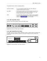
The function of each connector is explained below.
Aux Port connector
You may administer the ASG Guard Plus via a PC or terminal
connected to either the front- or back-panel Aux connector.
SIT
The SIT (System Initialization Tag) contains information, unique
to your ASG Guard Plus, that can be transferred to the ASG
Guard Plus by inserting the SIT connector.
Key switch
The key switch is used to turn the ASG Guard/ASG
Guard Plus on and off. The key can be removed in either
the on or off position. The ASG Guard Plus cannot be
turned on or off without a key.
LEDs
The LEDs display status messages. When the unit is operating
properly, the pulse LED will flash. The meaning of each LED is
explained in "LED Meanings," later in this chapter.
2.4.6 ASG Guard Plus Rear Panel
Figure 2-4 shows the rear panel connectors of a 16-port ASG Guard Plus, and Figure 2-5 shows
the rear panel connectors of a 28-port ASG Guard Plus.
Figure 2-4. 16-Port ASG Guard Plus Rear Panel Connectors
Figure 2-5. 28-Port ASG Guard Plus Rear Panel Connectors
Summary of Contents for Lucent Technologies Access Security Gateway Guard
Page 12: ...x Page intentionally left blank ...
Page 28: ...ASG Guard Overview 16 Page intentionally left blank ...
Page 36: ...Physical Connections 24 Page intentionally left blank ...
Page 60: ...Modem Port Setup 48 Page intentionally left blank ...
Page 82: ...Modifying the User Database 70 Page intentionally left blank ...
Page 120: ...Action and Event Tables 108 Page intentionally left blank ...
Page 158: ...User Connectivity 146 Page intentionally left blank ...
Page 188: ...Log Functions 176 Page intentionally left blank ...
Page 236: ...Troubleshooting 224 Page intentionally left blank ...
Page 252: ...Internal Battery Replacement 240 Page intentionally left blank ...
Page 258: ...Glossary of Command References 246 Page intentionally left blank ...


