background image

4

P

x

P

x

P

x

Port 5

Port 4

Port 3

Port 2

Port 1

3-p

i

n

ter

mi

nal

block

5 ports

10/100BASE-T(X)

R

J45 connectors

autonegot

i

aton

autopolar

i

ty

autocross

i

ng

LED d

i

splay ele

m

ents

P

P

10/100

DA/ST

A

T

Power

Data rate

Data, L

i

nk status

SPIDE

R

 5TX

SPIDE

R


8

TX

SPIDE

R

 4TX/1FX

SPIDE

R

 4TX/1FX-SM EEC

Port 7

Port 5

Port 3

Port 1

1 port

100BASE-FX

(port 1)

duplex-SC-

connector

full duplex

DA/ST

A

T

Port 1

DA/ST

A

T

P

10/100

DA/ST

A

T

10/100

DA/ST

A

T

10/100

DA/ST

A

T

10/100

DA/ST

A

T

10/100

DA/ST

A

T

10/100

DA/ST

A

T

10/100

DA/ST

A

T

10/100

DA/ST

A

T

10/100

DA/ST

A

T

Port 

8

Port 6

Port 4

Port 2

P

10/100

DA/ST

A

T

10/100

DA/ST

A

T

10/100

DA/ST

A

T

10/100

DA/ST

A

T

P

10/100

DA/ST

A

T

10/100

DA/ST

A

T

10/100

DA/ST

A

T

10/100

DA/ST

A

T

DA/ST

A

T

(Port 1)

3-p

i

n

ter

mi

nal

block

3-p

i

n

ter

mi

nal

block

8

 ports

10/100BASE-T(X)

R

J45 connectors

autonegot

i

aton

autopolar

i

ty

autocross

i

ng

LED d

i

splay

ele

m

ents

Port 5

Port 4

Port 3

Port 2

4 ports

10/100BASE-T(X)

R

J45 connectors

autonegot

i

aton

autopolar

i

ty

autocross

i

ng

P

x

P

x

DA/ST

A

T

SPIDE

R

 3TX

SPIDE

R

 1TX/1FX

SPIDE

R

 1TX/1FX-SM

Port 3

Port 2

Port 1

3-p

i

n

ter

mi

nal

block

3 ports

10/100BASE-T(X)

R

J45 connectors

autonegot

i

aton

autopolar

i

ty

autocross

i

ng

P

10/100

DA/ST

A

T

10/100

DA/ST

A

T

10/100

DA/ST

A

T

3-p

i

n

ter

mi

nal

block

Port 2

1 port

10/100BASE-T(X)

R

J45 connectors

autonegot

i

aton

autopolar

i

ty

autocross

i

ng

1 port

100BASE-FX

(port 1)

duplex-SC-

connector

full duplex

Port 1

P

10/100

DA/ST

A

T

DA/ST

A

T

(Port 1)

LED d

i

splay

ele

m

ents

P

10/100

DA/ST

A

T

= Power

= Data rate

= Data, L

i

nk 

   status

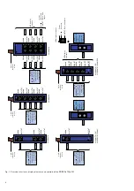
Fig. 1: Overview interfaces, display elements and controls

of the SPIDER xTX(/xFX)

Summary of Contents for Hirschmann SPIDER Series

Page 1: ...network segments to the TP ports using twi sted pair cabling The SPIDER 1TX 1FX devices have one 10 100 MBit s twisted pair port RJ45 connectors and one 100 MBit s fiber optic port 100BASE FX Duplex SC connector It is possible to connect one data terminal equipments or other network segments to the TP ports using twisted pair cabling One further DTE or optical network component can be connected to...

Page 2: ...scription and only in conjunction with external devices and components recommen ded or approved by Hirschmann The product can only be operated correctly and safely if it is transpor ted stored installed and assembled properly and correctly Furthermore it must be operated and serviced carefully Safety Guidelines Power Supply 䡺 Switch the basic devices on only when the case is closed z Warning The d...

Page 3: ...enginee ring standards trained or directed in the care and use of appropriate safety equipment in accor dance with the current standards of safety engineering trained in providing first aid General Safety Instructions 䡺 This device is electrically operated Adhere strictly to the safety requirements relating to voltages applied to the device as described in the operating instructions z Warning Fail...

Page 4: ...T 10 100 DA STAT DA STAT Port 1 3 pin terminal block 3 pin terminal block 8 ports 10 100BASE T X RJ45 connectors autonegotiaton autopolarity autocrossing LED display elements Port 5 Port 4 Port 3 Port 2 4 ports 10 100BASE T X RJ45 connectors autonegotiaton autopolarity autocrossing P x P x DA STAT SPIDER 3TX SPIDER 1TX 1FX SPIDER 1TX 1FX SM Port 3 Port 2 Port 1 3 pin terminal block 3 ports 10 100B...

Page 5: ...rs the age of the learned addresses The SPIDER deletes address entries from the address table which exceed a certain age 300 seconds Note Restarting deletes the learned address entries Tagging IEEE 802 1Q The IEEE 802 1 Q standard designates the VLAN tag to be included in a MAC data frame for the VLAN and prioritizing func tions The VLAN tag consists of 4 bytes 2 bytes tag protocol identifier TPID...

Page 6: ...er snap on slide bar of the SPIDER to the standard bar and press it down until it locks in position 䡺 Fit the signal lines Notes The SPIDER is grounded via a pin of the terminal block Do not open the housing The shielding ground of the twisted pair lines which can be connected is electrical ly connected to the ground connection Fig 5 Assembling the SPIDER Fig 6 Dimensions 13 7 70 63 3 23 8 5 3 3 S...

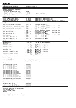
Page 7: ...b SPIDER 4TX 1FX Ambient temperature 0 ºC to 60 ºC 32 ºF to 140 ºF SPIDER 3TX TAP SPIDER 5TX SPIDER 8TX Surrounding air SPIDER 1TX 1FX SPIDER 1TX 1FX SM SPIDER 4TX 1FX 40 ºC to 70 ºC 40 ºF to 158 ºF SPIDER 4TX 1FX EEC SPIDER 4TX 1FX ST EEC SPIDER 4TX 1FX SM EEC SPIDER 5TX EEC SPIDER 8TX EEC 40 ºC to 75 ºC 40 F to 167 F SPIDER 1TX 1FX EEC SPIDER 1TX 1FX SM EEC Storage temperature 40 ºC to 70 ºC 40 ...

Page 8: ...connection 100 MBit s singlemode SM SPIDER 3TX TAP 3 TP TX ports RJ45 sockets 10 100 MBit s SPIDER 5TX SPIDER 5TX EEC 5 TP TX ports RJ45 sockets 10 100 MBit s SPIDER 8TX SPIDER 8TX EEC 8 TP TX ports RJ45 sockets 10 100 MBit s Displays Equipment status 1 x green LED P power supply voltage present Port status SPIDER 1TX 1FX 2 x green LEDs DA STAT data link status 1 x yellow LEDs 10 100 data rate TP ...

Reviews: