background image

46

Technical Details

Environmental Specifications

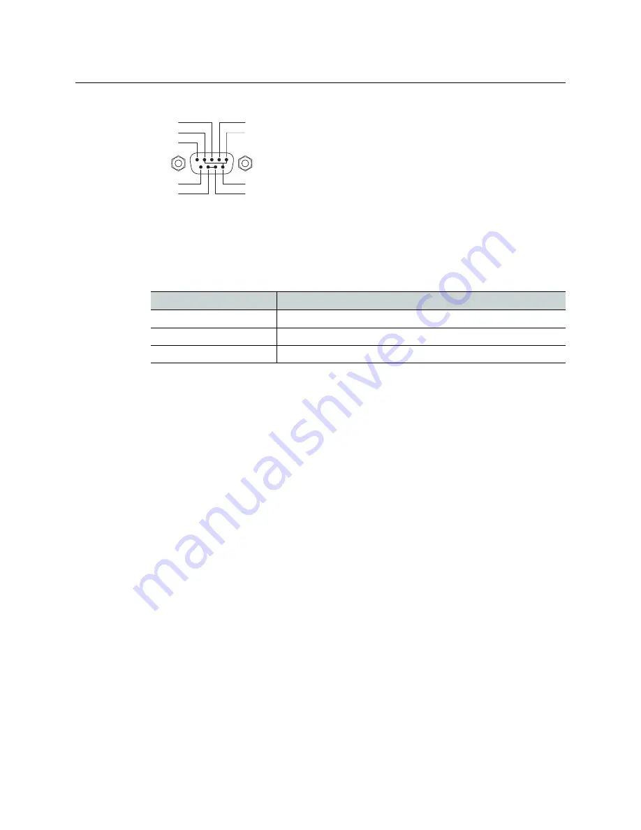
The RS-232 connector has this pinout: 

Pins 1, 4, and 6 are tied together and pins 7 and 8 are tied together. None of those pins are 
connected to any circuitry.

Environmental Specifications

NV9603 Environmental Specifications 

Defaults 

Initial Panel State 

Destination: the configured default.
Buttons: low-tally is 40% brightness by default and stays at its most recent setting.

Configuration Page 

The initial NV9603 configuration has no buttons defined. The default panel options are:

Release mode:

Normal.

Default destination: 

None.

Preset monitor: 

None.

Status monitor: 

None.

Data routing mode:

Automatic.

Salvo List: 

None.

Default name set:

System names.

Other options:

All disabled except ‘Use Continuous Scrolling’.

DHCP 

The panel is set up to respond to DHCP from the factory. It is possible to assign the panel a 
fixed IP address using the Panel IP Configuration Utility. 

Drawings 

The drawings on the following page provide overall and critical dimensions. 

n.c.

1

5

9

6

Tx

Rx

Gnd

n.c.

n.c.

n.c.

n.c.

n.c.

Specification

Detail

Operating temperature

0–30


° C, ambient.

Relative humidity

0 to 90%, non-condensing.

Cooling

No fan required.

Summary of Contents for Grass Valley NV9603

Page 1: ...www grassvalley com User s Guide VERSION 1 2 UG0041 02 2015 07 02 NV9603 NV9000 CONTROL PANEL...

Page 2: ...license to owners of NVISION control panels to use their product manuals for their own internal business use Manuals for Grass Valley products may not be reproduced or transmitted in any form or by a...

Page 3: ...any fluid leaks out of a damaged glass cell be careful not to get the liquid crystal fluid in your mouth or skin If the liquid crystal touches your skin or clothes wash it off immediately using soap...

Page 4: ...th this equipment meet the appropriate national standards for the country of destination Electromagnetic Compatibility This equipment has been tested for verification of compliance with FCC Part 15 Su...

Page 5: ...uency electromagnetic field immunity EN 61000 4 4 Electrical fast transient immunity EN 61000 4 5 Surge transient immunity EN 61000 4 6 Conducted disturbances immunity EN 61000 4 8 Power frequency mag...

Page 6: ...vi Notices...

Page 7: ...3 Functions 5 3 Installation 7 Package Contents 7 Installation 8 Installing Software and Documentation 8 Initialization 8 Testing 9 4 Configuration 11 Summary 11 Adding a Panel to an NV9000 Configurat...

Page 8: ...ons 29 Broadcast 29 Category 30 Chop 30 Clear 30 Destination 31 Destination Lock 31 Destination Protect 31 Destination Mode 32 Destination Shift 32 Free Source 32 Level 32 Menu 32 Name Set Toggle 32 P...

Page 9: ...9 Menu Mode 40 Panel ID 40 Panel Name 41 User ID 41 User Name 41 Software Versions 41 Button Illumination 42 Setup Mode 42 6 Technical Details 45 Power Specifications 45 NV9603 Specifications 45 Envir...

Page 10: ...x Table of Contents...

Page 11: ...Technical Details provides electrical mechanical and environmental specifications product drawings and default settings An index and glossary are also provided for your reference The PDF Document This...

Page 12: ...guide The term control panel refers to the NV9603 control panel and to NV96xx control panels in general High tally means that a button is brightly illuminated Low tally means that a button is illumin...

Page 13: ...t the lower left are category buttons by convention The two buttons immediately to the left of the display are scroll buttons Page Up and Page Down by default Using the scroll buttons the operator can...

Page 14: ...tally green or amber and off Operators can adjust the low tally levels in increments of 10 using the panel s menu Buttons that are turned off are said to be dark Physically they are actually white or...

Page 15: ...Modes of Operation The NV9603 operates in X Y mode Additional but secondary modes of panel operation are Salvo mode pressing a salvo button places the NV9603 in salvo mode where the operator may sele...

Page 16: ...6 Introduction Other NV9603 Functions...

Page 17: ...issing or if you find equipment damage unrelated to shipping please contact technical support Depending on your order the NV9603 items that can ship include One or more NV9603 control panels An AC pow...

Page 18: ...if you want to your NV9603 to have a static IP address with respect to the system controller or to use DHCP The panel as it comes from the factory defaults to DHCP Initialization Before your system c...

Page 19: ...luminate When an NV9603 powers up one or more of its buttons are supposed to turn green or amber Did it pass the panel test mentioned above 2 When the NV9603 powers up and it is connected to the syste...

Page 20: ...10 Installation Testing...

Page 21: ...he NV9603 is a relatively simple panel It has 34 function buttons and a small display It operates in X Y mode NV9000 SE Utilities is the software with which to configure the NV9603 Figure 4 1 followin...

Page 22: ...eld In the ID field enter the panel ID you assigned to the panel while it was in setup mode You can change the panel ID in NV9000 SE Utilities Give a name to the panel in the name field and select a u...

Page 23: ...ious page Click Cancel to terminate the entry operation There are 2 other buttons Suffix and Navigate both dim disabled These do not apply to the NV9603 Return to the Control Panels page to view your...

Page 24: ...e two important configuration buttons Revert to Saved and Save The Save button commits modifications you have just made The Revert to Saved button restores the last saved version of the panel configur...

Page 25: ...erators use a Source Shift button to switch between the 2 pages of sources and use a Destination Shift button to switch between the 2 pages of destinations When you are configuring a source button the...

Page 26: ...emi automatic recommended If the control port is in use on the source or destination device take all levels except control and allow the user to perform the control level route by pressing Take a seco...

Page 27: ...e control takes Hide sources not configured on this panel Causes the names of source devices that are not presently configured for this particular panel to be effectively hidden When another panel cha...

Page 28: ...Salvo Button Specification The button definition section configures the button you have selected in the image of the NV9603 When you choose a button type additional drop down menus can appear dependin...

Page 29: ...ory buttons represent suffixes If your category button does not represent a suffix select None in the Suffix field If your category button does not represent a source category select None in the sourc...

Page 30: ...not operate in multi destination mode It is present on the configuration page as a future feature Destination Mode The button places the panel in destination mode in which category selection buttons...

Page 31: ...he NV9603 panel in menu mode and displays a menu that provides access to certain panel functions Without the button the operator has no access to the menu functions By pressing certain buttons the ope...

Page 32: ...e next higher device would probably be CAM_4 subject to the device definitions in the NV9000 configuration Scrolling devices is possibly only when a category selection is in progress Whether the list...

Page 33: ...stination is the master This button and these concepts apply only to machine control routes The button definition has no fields to configure The button is a toggle Press it once to make the source the...

Page 34: ...ton routes the preset source to the selected destination on selected level or levels In salvo mode a take button executes a selected salvo A take button is disabled and dark until it is possible for t...

Page 35: ...menu items in other cases See Alphanumeric Display on page 4 for information Physically you will find Function buttons e g select a source or lock a destination Source destination and category buttons...

Page 36: ...with setup mode See Setup Mode on page 42 Menu mode pressing a menu button places the NV9603 in menu mode In menu mode the buttons lose their normal functions and become part of a menu that changes as...

Page 37: ...ousands of sources and destinations common in many installations Device categories exist to solve that problem A device belongs to a named category and has an identifier within that category Typically...

Page 38: ...e Some devices such as VTRs are both sources and destinations There are 3 button types that affect category device selection Source Mode places the panel in source mode Destination Mode places the pan...

Page 39: ...The remedy is to reselect the destination Doing so causes the pending take to become all level once again Buttons The NV9603 has 3 classes of button functions Dedicated functions such as Default State...

Page 40: ...set field of the display as the beginning of a device name 2 Press one or more suffix buttons to complete the selection within that category For instance for device VTR_12 press a VTR category button...

Page 41: ...lso go high tally amber Locks can apply to selected levels in limited X Y mode The NV9603 provides no explicit indication during operation whether a destination is locked or unlocked Destination Prote...

Page 42: ...ed for limited X Y mode Presumably it will have several level buttons one for each level you need to control You will select one or more levels for a breakaway and then press a source button to comple...

Page 43: ...crolling varies with context Scrolling devices within a category Page Up moves to the next higher device in the category s device list Example if the current device is CAM_3 the next lower device woul...

Page 44: ...button is affected by whether your panel has a Source Shift button and its state whether it is selected or not Source is Master Means source is the master and makes the source device the master Otherw...

Page 45: ...ly category suffixes See Device Selection by Category on page 27 Take In normal mode a take button routes the preset source to the selected destination on selected level or levels In salvo mode a take...

Page 46: ...vels or all levels 4 Press a Destination Lock button Use this same method to protect or unprotect selected levels using a Destination Protect button instead Note that lock buttons are toggles Therefor...

Page 47: ...name the panel displays the system name Broadcast Routes It is easy to route a source to multiple destinations for audio and video routers You place the panel in hold mode with the hold button In con...

Page 48: ...the source device manually The panel provides no way to determine which devices belong to the broadcast group You must keep track of this yourself If another operator takes either your master device...

Page 49: ...ill time out if you do not press the source button Chop The chop function is a diagnostic function for routers that support chop It allows you to switch rapidly between two sources at a particular des...

Page 50: ...ser ID User name Software version Boot version Application version Low button illumination level Configurers should ensure that the menu button is not part of the numeric keypad that becomes available...

Page 51: ...e it User Name The fourth submenu merely displays the configured user name You cannot change it Software Versions The fifth submenu displays the software version The sixth submenu displays the boot ve...

Page 52: ...p the panel leaves menu mode and returns to normal mode Configurers note it is important not to locate the menu button on any of the buttons used to change the illumination Setup Mode Setup mode occur...

Page 53: ...ep Following the panel ID is the display of the software version The software part number and its revision number wrap around the first two lines of the display In the illustration above the part numb...

Page 54: ...The button will flash a few times rapidly Pressing the setup button will terminate the button test and return you to the initial display of setup mode At this point if you have a assigned your NV9603...

Page 55: ...Hz auto sensing Inrush current 50 A at 230 VAC cold start at 25 C Input current 2 0 A rms at 115 VAC 1 0 A at 230 VAC Power consumption 14 W Regulatory UL listed and CE compliant Specification Detail...

Page 56: ...no buttons defined The default panel options are Release mode Normal Default destination None Preset monitor None Status monitor None Data routing mode Automatic Salvo List None Default name set Syst...

Page 57: ...47 NV9603 User s Guide Fig 6 1 Front View of the NV9603 1 72 43 7 19 0 482 6...

Page 58: ...48 Technical Details Drawings Fig 6 2 Top and Rear Views of the NV9603 1 72 43 7 19 0 482 6 17 38 441 5 8 61 218 7 9 14 232 2 1 25 31 8...

Page 59: ...e NV9603 Level set A level set is a group of virtual levels that are commonly used together when switching devices A level set also defines the mapping of each virtual level within the level set to a...

Page 60: ...llumination 2 Tally interface to be defined Virtual level Virtual levels allow the system administrator to define a single physical router level as multiple levels Within a physical level any port can...

Page 61: ...9 29 31 destination lock 20 31 36 destination mode 20 32 destination protect 20 31 36 destination shift 20 27 32 finish 13 free source 5 20 32 level 21 32 menu 5 21 26 29 32 40 name set toggle 5 21 32...

Page 62: ...Default destination 16 46 NV9603A configuration page 14 46 source is master 17 Default name set 32 37 Default name set option 16 46 Defaults 46 Destination buttons 25 default 16 46 locks 35 protects...

Page 63: ...8 install the NV9603A 8 make a broadcast route 38 perform a take 36 use semi automatic data routing mode 39 Hyperlinks Acrobat 1 I ID panel 8 9 17 21 26 32 40 43 44 ID user 40 Illumination submenu 42...

Page 64: ...ame set toggle button 5 21 32 37 Name set default 32 37 Name sets 16 21 37 46 Next button 13 Next page Acrobat 1 Next view Acrobat 1 No server message 9 Normal mode 5 24 26 40 Normal release 16 NotOwn...

Page 65: ...message 31 Protects 5 31 35 destination 35 source 35 R Rack mount 8 Receiving and unpacking shipments 7 Release 5 35 36 forced 16 31 35 36 49 mode 16 46 normal 16 Retry message 39 Revert to saved but...

Page 66: ...lvos 5 T Tables environmental specifications 46 Take button 23 24 35 Takes 36 49 Tally 2 Technical support 57 Temperature operating 46 Terms conventions and abbreviations 2 Testing your installation 9...

Page 67: ...n a local phone number for the support center nearest you please consult the Contact Us section of Grass Valley s website www grassvalley com An online form for e mail contact is also available from t...

Reviews: