Belden GRASS VALLEY HDA-3911 Manual To Installation And Operation Download Page 12

GUIDE TO INSTALLATION AND OPERATION 
 

8

  |  HDA-3911/31 


3.3  Local control using the Densité 3 frame control panel 

3.3.1  Overview 

 
Push the SELECT button on the HDA-39x1 card edge 
(see Section 1.4) to assign the local control panel to 
operate the HDA-39x1. Use the control panel buttons to 
navigate through the menu, as described below. 
 
All of the cards installed in a Densité 3 frame are 
connected to the frame’s controller card, which handles 
all interaction between the cards and the outside world. 
There are no operating controls located on the cards 
themselves. The controller supports remote operation 
via its Ethernet ports, and local operation using its 
integrated control panel. 
 
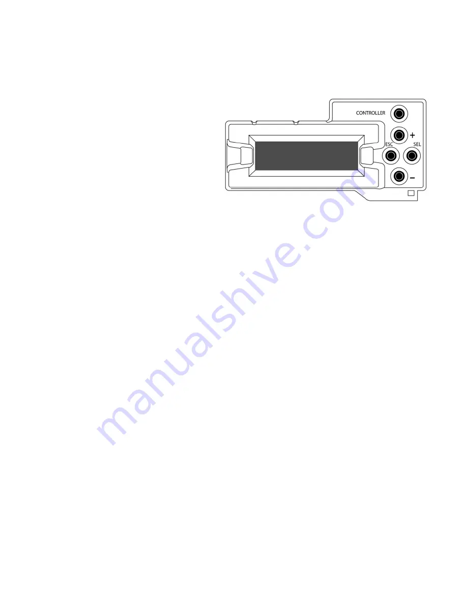
The local control panel is fastened to the front of the 
CPU-ETH2 controller card, and when installed is located in the front center of the frame, positioned in front of the 
power supplies. The panel consists of a display unit capable of displaying two lines of text, each 16 characters in 
length, and five pushbuttons. 
 
The panel is assigned to operate any card in the frame by pushing the SELECT button on the front edge of that card.  


Pushing the CONTROLLER button on the control panel selects the Controller card itself.  


The STATUS LED on the selected card flashes yellow. 

 
The local control panel displays a menu that can be navigated using the four pushbuttons located beside the display. 
The functionality of the pushbuttons is as follows: 
 
[+]  [–] 

Used for menu navigation and value modification  

 
[SELECT]  Gives access to the next menu level. When a parameter value is shown, pushing this button once 

enables modification of the value using the [+] and [–] buttons; a second push confirms the new value 

 
[ESC] 

Cancels the effect of parameter value changes that have not been confirmed; pushing [ESC] causes the 
parameter to revert to its former value. 


Pushing [ESC] moves the user back up to the previous menu level. At the main menu, [ESC] does 

not


exit the menu system. To exit, re-push the [SELECT] button for the card being controlled. 

 
If no controls are operated for 30 seconds, the controller reverts to its normal standby status, and the selected card’s 
STATUS LED reverts to its normal operating mode. 
 

3.3.2  Menu for local control 

 
The HDA-39x1 has operating parameters which may be adjusted locally at the controller card interface.  


Press the SELECT button on the HDA-39x1 front card edge to assign the Densité 3 frame’s local control 
panel to the HDA-39x1 


Use the keys on the local control panel to step through the displayed menu to configure and adjust the HDA-
39x1.  

 
The complete menu structure is shown in Annex 1 to this document, beginning on page 20. 

Figure 3.1  Densité 3 Frame local control panel 

Summary of Contents for GRASS VALLEY HDA-3911

Page 1: ...HDA 3911 3931 Single Dual 3G HD SD SDI Distribution Amplifiers Guide to Installation and Operation M3056 9900 100 2015 08 21 ...

Page 2: ...manual may cause harmful interference to radio communications Operation of this equipment in a residential area is likely to cause harmful interference in which case the user will be required to correct the interference at his own expense This equipment has been tested and found to comply with the requirements of the EMC directive 2004 108 CE EN 55022 Class A radiated and conducted emissions ENV 5...

Page 3: ... 3 2 Card Edge Status LED 7 3 3 Local control using the Densité 3 frame control panel 8 3 3 1 Overview 8 3 3 2 Menu for local control 8 3 4 Remote control using iControl 9 3 4 1 The iControl graphic interface window 9 3 4 2 The Input panel 11 3 4 3 The Rear panel 12 3 4 4 The Status panel 12 3 4 5 The Output panel 13 3 4 6 The Alarms panel 13 3 4 7 The Info panel 16 3 4 8 The Presets panel 17 4 Sp...

Page 4: ...GUIDE TO INSTALLATION AND OPERATION HDA 3911 31 ...

Page 5: ... are required the HDA 3911 3931 are ideal since they can natively offer fiber connectivity Additional protection for critical applications is provided by an optional protection bypass relay available on selected rears The HDA 3911 3931 will also support DVB ASI on selected outputs 1 2 Features One HDA 3911 or two HDA 3931 inputs Up to nine 3GHD SD SDI outputs Supports bit rates all the way up to 2...

Page 6: ...31 Functional Block Diagram 1 4 Front Card edge Interface The front card edge of the HDA 3911 31 incorporates two elements Status LED see section 3 2 Select Button see section 3 3 Select Button IRD 3802 Status LED Status Select HDA 3911 Figure 1 2 Front card edge layout ...

Page 7: ...support For the HDA 3931 HDA 393N 3SRP Single rear for dual 1x3 operating mode HDA 393N 3SRP F Single rear for dual 1x3 operating mode with fiber option support HDA 393N 3DRP Double rear for dual 1x4 operating mode All cards and rear panels can be installed with the frame power on The card has connectors which plug into a mid frame mother board for distribution of power and for connection to the c...

Page 8: ...e the HDA 39x1 card into the slot and push gently on the handle to seat the connectors If the card is used with a double width rear panel 3DRP it should be inserted into the right hand slot Inserting the card into the wrong slot will not damage the card and will be flagged by the on card status LED flashing red to indicate that there is no connection to the rear panel 3 Close the front panel of th...

Page 9: ...ons on the various rear panels shown above I O Connections Use with Rear panel type 3G HD SD SDI IN 3G HD SD SDI OUT FIBER I O Bypass HDA 3911 HDA 3931 HDA 391N 3SRP 1 7 HDA 391N 3SRP R 1 7 HDA 391N 3SRP F 1 5 HDA 393N 3SRP 2 2 x 3 HDA 393N 3SRP F 2 2 x 3 HDA 393N 3DRP 2 2 x 4 Note that the HDA 393N 3SRP F panel uses DIN1 0 2 3 connectors on outputs A2 A3 and B2 B3 All other electrical connectors ...

Page 10: ...ber I O connector accepts any of the available SFP cartridges At the time of publication of this document the following cartridges were available SFP R LC Single fiber Rx input cartridge with LC PC connector SFP RR LC Dual fiber Rx input cartridge with LC PC connector SFP T S13 LC Single fiber Tx output cartridge at 1310 nm with LC PC connector SFP TT S13S13 LC Dual fiber Tx output cartridge at 13...

Page 11: ...ous error conditions that can be flagged on the HDA 39x1 affect the LED status If a cell is gray the error condition cannot cause the LED to assume that status If more than one LED status is possible for a particular error condition the status is configurable See Section 3 4 6 for details The factory default status is shown by a The LED will always show the most severe detected error status that i...

Page 12: ...d card flashes yellow The local control panel displays a menu that can be navigated using the four pushbuttons located beside the display The functionality of the pushbuttons is as follows Used for menu navigation and value modification SELECT Gives access to the next menu level When a parameter value is shown pushing this button once enables modification of the value using the and buttons a secon...

Page 13: ...igure 3 2 The window identification line gives the card type HDA 3911 or HDA 3931 and the slot number where the card is installed in its Densité frame Figure 3 2 HDA 3931 iControl graphic interface window There are three main sections in the window itself shown in Figure 3 2 1 The top section displays icons on the left These icons report the status of some parameters associated with this HDA 39x1 ...

Page 14: ...rface will have no effect on the card Icon 2 Input A status green Signal detected and valid Beneath the icon the format will be indicated as 3G HD or SD and the specific format details will be listed if the cursor is moved over the icon red Input signal error No rear grey No electrical input Icon 3 Input B status only on HDA 3911 green Signal detected and valid Beneath the icon the format will be ...

Page 15: ...HDA 39x1 HDA 3911 Only one channel is available so channel B does not appear in the panel HDA 3931 Two channels are available The rear panel may have one or two electrical inputs and may have two optical inputs Channel B will be greyed out if no signal is available for it Input Config Select the input for Channel A and Channel B using the radio buttons Electrical Input A and Optical Input A can on...

Page 16: ...status of the various inputs to this HDA 39x1 For HDA 3911 only IN A is shown because there is no IN B Electrical inputs A and B Data rate 270 Mbps 1 5 Gbps 3 Gbps the detected input data rate is indicated by a green status icon No Lock No Signal either of these conditions is indicated by a red status icon Fiber Module type the type of fiber module installed in the rear panel will be shown in the ...

Page 17: ...ector and an installed output TX cartridge Optical output A if available can only carry channel A Optical output B if available can carry either Channel A or Channel B on an HDA 3931 and the choice is made here On an HDA 3911 only channel A is available because there is no channel B 3 4 6 The Alarms panel This panel allows the alarm reporting of the HDA 39x1 to be configured Click on the Alarm Con...

Page 18: ...Alarm Status associated with this card GSM is a dynamic register of all iControl system alarms and is also an alarm provider for external applications The possible values for this contribution are related to the Overall alarm contribution If the Overall alarm contribution is selected as Disabled the GSM alarm contribution can be set to any available value If the Overall alarm contribution is selec...

Page 19: ...o open a save dialog where you can save a file containing a list of all alarms on this card and their current values along with an Alarm Key for each The alarm keys are useful for system integration and troubleshooting The file is saved in csv format OK Apply Cancel OK accepts the settings and closes the window once the card confirms that there are no errors Apply accepts the settings but leaves t...

Page 20: ...n for this HDA 39x1 when it appears in iControl applications Short Label type the short form label that iControl uses in some cases 8 characters Source ID type a descriptive name for this HDA 39x1 Comments type any desired text The remaining data boxes show manufacturing information about this card Three buttons in the panel give access to other information Details Reports the Firmware version ser...

Page 21: ...om the window You will be asked to confirm the removal in a Query box 3 4 8 The Presets panel User Presets The HDA 39x1 has memory registers which can hold up to 5 user defined parameter settings Select any one of the five presets using the pull down list The name of the currently selected User Preset is shown on the name bar Click Load to load the contents of the selected User Preset into the HDA...

Page 22: ... 2967 2970Mb s EN50 83 9 DVI ASI 270 Mbps Cable length 15km of SMF fiber 9 125 at wavelengths between 1260nm and 1600nm ELECTRICALOUTPUTS 9 Signal 3G HD SD SDI SMPTE 424M 292M and 259M C compliant Supports data rates of 270 1483 5 1485 2967 2970Mb s EN50 83 9 DVI ASI 270 Mbps 5 outputs only Return loss 15 dB for up to 1 5GHz 10 dB from 1 5GHz to 3GHz Jitter wideband 0 2 UI p p Rise Fall time 135 p...

Page 23: ... or 1 530 478 4148 To obtain a local phone number for the support center nearest you please consult the Contact Us section of Grass Valley s website www grassvalley com An online form for e mail contact is also available from the website Corporate Head Office Grass Valley 3499 Douglas B Floreani St Laurent Quebec H4S 2C6 Canada Telephone 1 514 333 1772 Fax 1 514 333 9828 www grassvalley com ...

Page 24: ...TX FIBER RX A TX B FIBER IN A NO LOCK NO SIGNAL 270 Mbps 1 5 Gbps 3 Gbps INPUT CONFIG INPUT A ELECTRICAL A OPTICAL A OUTPUT CONFIG OPTICAL A ON OFF OPTICAL B ON OFF RECLOCKER RECLOCKER A ON BYPASS USER PRESET LOAD USER 1 USER 2 USER 3 USER 4 USER 5 SAVE USER 1 USER 2 USER 3 USER 4 USER 5 CONFIG ALARMS CH A NO LOCK ALARM LEVEL GREEN YELLOW RED FLASH RED ALARM REPORT NONE GPI CH A NO SIGNAL ALARM LE...

Page 25: ...B INPUT B ELECTRICAL B OPTICAL B OUTPUT CONFIG OPTICAL A OFF ON OPTICAL B OFF ON RECLOCKER RECLOCKER A ON BYPASS RECLOCKER B ON BYPASS OPERATING MODE DUAL CHANNEL SINGLE CHANNEL USER PRESET LOAD USER 1 USER 2 USER 3 USER 4 USER 5 SAVE USER 1 USER 2 USER 3 USER 4 USER 5 CONFIG ALARMS CH A NO LOCK ALARM LEVEL GREEN YELLOW RED FLASH RED ALARM REPORT NONE GPI CH A NO SIGNAL ALARM LEVEL GREEN YELLOW RE...

Page 26: ... it is installed DO NOT LOOK INTO AN OPERATING SFP MODULE S CONNECTORS AS EYE DAMAGE MAY RESULT The SFP module is sensitive to electrostatic discharge ESD It is recommended that you use an ESD preventive wrist strap grounded to the Densité 3 chassis while handling the SFP module SFP modules are subject to wear and their useful lifetime is reduced each time they are inserted or removed Do not remov...

Page 27: ...1 Grasp the LC fiber optic connector that is plugged into the SFP module and pull it straight out to disengage the optical fiber from the SFP Never pull the fiber optic cable itself as catastrophic damage may occur 2 Insert a dust plug into the SFP module Removing the SFP module 1 Move the latch to the open position 2 Grasp the SFP module between your thumb and forefinger and pull it straight out ...

Reviews: