background image

GUIDE TO INSTALLATION AND OPERATION 
 

32

  |  ADX-1901 

Copy profile from 

 
This line shows this ADX-1901  card, and identifies it by App server, Densité frame and slot number, card type and 
firmware version. 


The 

Profile

 column has a pulldown that allows you to select which profiles you will work with, and gives these choices:  


Current, User1, User2, User3, User4, User5, All 

 
The 

Select

 column includes a checkbox (preselected checked) to confirm that you want to work with the current card. 


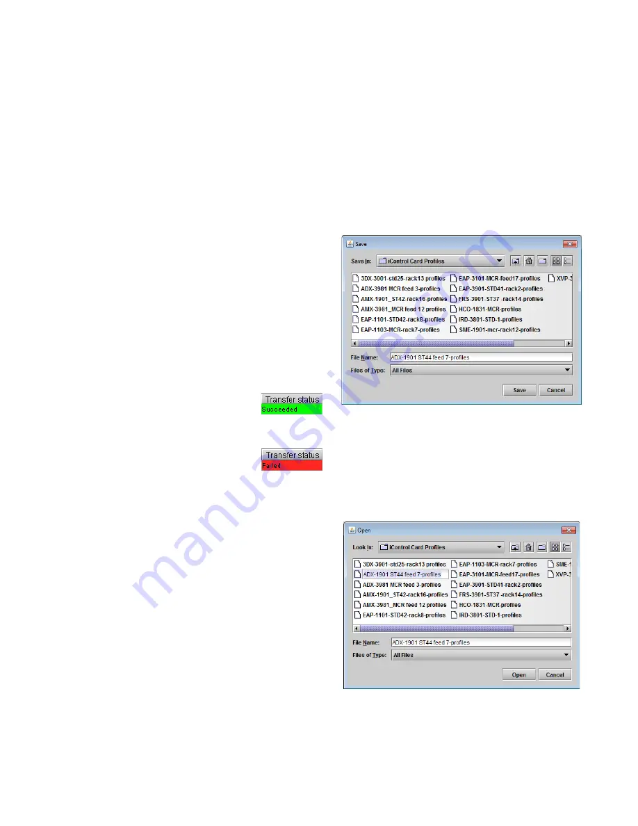
Save Profile to Disk… 

 
Click this button to open a Save dialog allowing you to specify a 
file name and location to which the selected profiles for this 
card will be saved. 
 

Hint - It is a good idea to create a folder for these files, because 
they are not explicitly identified as ADX-1901 profiles, and will 
be difficult to find and identify if not clearly named and 
conveniently located.  


Click the save button once the name and location have 

been identified in the Save box 


If the file is saved correctly, the Transfer Status box on 

the right of the 

Copy profile from

 line will indicate 

Succeeded

 against a green background: 


If the file was not saved for some reason, the Transfer 

Status box to the right of the 

Copy profile from

 line will 

indicate 

Failed

 against a red background: 


Restore profiles from disk… 

 
Click this button to open an 

Open

 dialog box within which you 

can locate and select a valid ADX-1901 profile file. 


Click Open to read the contents of the file and to 

reconfigure this ADX-1901’s profiles according to its 
contents 


While the reconfiguration is in progress, the Transfer 

Status box on the right of the 

Copy profile from

 line will 

indicate 

Working

 against a yellow background 


When the reconfiguration is complete, the Transfer Status 

box on the right of the 

Copy profile from

 line will indicate 

Succeeded

 against a green background 

 
Copy Profile to 
 

This line shows other ADX-1901 cards that are available on the 
iControl network, each identified by App server, Densité frame 
and slot number, card type and firmware version


Figure 5-29 Save Profile to Disk dialog 

Figure 5-30 Restore Profiles from Disk dialog 

Summary of Contents for GRASS VALLEY ADX-1901

Page 1: ...ADX 1901 3G HD SD 8 Channel Analog Audio De Embedder Guide to Installation and Operation M3005 9900 101 2015 04 29...

Page 2: ...nual may cause harmful interference to radio communications Operation of this equipment in a residential area is likely to cause harmful interference in which case the user will be required to correct...

Page 3: ...the Densit frame control panel 9 4 1 Overview 9 4 2 Menu for local control 10 5 Remote control using iControl 11 5 1 The iControl graphic interface window 11 5 2 Video Input Output panel 13 5 2 1 Vide...

Page 4: ...panel 30 5 12 Factory Presets panel 31 5 13 Alarm Config panel 33 5 14 Info panel 36 6 Specifications 38 7 Grass Valley Technical Support 40 ANNEX 1 ADX 1901 Local User Interface 41 ANNEX 2 Installing...

Page 5: ...e with the Densit 3 frame with the metal extender Multiple rear connector panels are available according to your application needs and the chassis type used A fiber input output cartridge is offered a...

Page 6: ...Figure 1 1 ADX 1901 Functional Block Diagram 1 4 Front Card edge Interface The front card edge of the ADX 1901 incorporates two elements Status LED see section 3 2 Select Button see section 4 Figure...

Page 7: ...e In this case only a single slot width panel is required Two rear panels are available ADX 1901 3SRP Single slot width panel for Densit 3 ADX 1901 3SRP F Single slot width panel for Densit 3 with fib...

Page 8: ...3 frame ADX 1901 3RU it will be delivered with an installed adapter that allows it to fit into the taller frame The adapter can be ordered separately and user installed if required Once a matching rea...

Page 9: ...described below 2 4 2 Summary of rear panel connections ADX 1901 3SRP ADX 1901 3SRP F ADX 1901 DRP ADX 1901 DRP F Single slot width panel Double slot width panel CONNECTORS 3G HD SD IN 1 1 1 1 3G HD...

Page 10: ...g audio outputs 8 The eight analog audio outputs are balanced outputs via a 26 pin D SUB female connector Pinout for the connector is shown in the table Fiber I O Fiber optic inputs and outputs Rear p...

Page 11: ...fiber Rx input and Tx output module at 1310 nm with LC PC connectors SFP R LC Single fiber Rx input module with LC PC connector SFP RT W13 LC Single fiber Rx Tx module at 1310 nm with WDM LC PC connec...

Page 12: ...ADX 1901 affect the LED status If a cell is gray the error condition cannot cause the LED to assume that status If more than one LED status is possible for a particular error condition the status is c...

Page 13: ...ing controls located on the cards themselves The controller supports remote operation via its Ethernet ports and local operation using its integrated control panel The local control panel is fastened...

Page 14: ...SC does not exit the menu system To exit re push the SELECT button for the card being controlled If no controls are operated for 30 seconds the controller reverts to its normal standby status and the...

Page 15: ...ow structure for the ADX 1901 is shown in figure 5 1 The window identification line gives the card type ADX 1901 and the slot number where the card is installed in its Densit frame There are four main...

Page 16: ...Icon interpretation Icon 1 Manual Card Configuration green Remote card control activated The iControl interface can be used to operate the card yellow Local card control active The card is being contr...

Page 17: ...hen displays the group s set of parameters Each of the groups is described in detail below Section 3 The lower left corner of the window identifies the Preset currently in use or Custom if none is app...

Page 18: ...n a receiver SFP module is installed Fiber Output Config This control is only available when a transmitter SFP module is installed The fiber Out 2 selector is only available when a dual transmitter SF...

Page 19: ...TC 3G HD embedded in the SDI input The Timecode De embedding section provides resources to configure the de embedding process Delay Adjust the timecode delay value to compensate for a 1 to 50 frame of...

Page 20: ...output state is inactive o De embed the GPI data located on a pre defined user bit within timecode in the incoming SDI signal is de embedded When De embed is selected use the Bit pulldown list to set...

Page 21: ...Signal Presence indicates the presence of audio in the 16 channels that may be carried in the embedded audio groups Green audio present Gray audio not present for 2 seconds minimum 5 4 1 CH 1 4 5 8 9...

Page 22: ...el adjustment mixing 5 5 1 1 2 3 4 5 6 7 8 tabs Each of these tabs provides all necessary controls for the output mixers The example shown is for 1 2 output but all panels have the same controls Opera...

Page 23: ...high level at the output resulting in signal clipping Source A Source B These sub sections allow the source channels A and B to be selected for each output channel Channel CH 1 CH 16 selects the demu...

Page 24: ...X X OFF This program is not used The graphic at the bottom of the panel illustrates the selected programs and provides pull downs to choose the audio input that feeds each program input Note 1 An inpu...

Page 25: ...nual Downmix follows the downmix parameters manually configured by the user Level Normalization use the pulldown to select the type of normalization to be applied on the downmix output level OFF Downm...

Page 26: ...und Level Center Level Ls Rs Lo Ro L R C Surround Level LFE Level LFE Figure 5 12 Lo Ro downmixer 5 8 Loudness Panel The ADX 1901 allows the user to measure the loudness of audio streams passing throu...

Page 27: ...the Audio Programs tab Note that segment marker triggers in one PGM will generate segment markers in the logs for all PGMs Logging Status Control This panel monitors logging activity for all loggers...

Page 28: ...of the last 15 seconds of the value of the Short Term yellow trace and Momentary green trace loudness values The bar graph at the right indicates the current Momentary value A reset initiated by a us...

Page 29: ...d by the status LED on the card edge when a Black Detect alarm is set Choices are Green Yellow Red Flashing Red Zone settings define a zone within which the alarm detection will be applied Line Start...

Page 30: ...tus LED on the card edge when a DVITC ATC alarm is set Choices are Green Yellow Red Flashing Red 5 9 3 Alarms Audio panel The Audio alarms are detected after the Audio Output stage just before the Dig...

Page 31: ...continuously present to clear the alarm if it has been set Use the LED Color pulldown to choose the color that will be displayed by the status LED on the card edge when a Max Level alarm is set Choice...

Page 32: ...o choose the color that will be displayed by the status LED on the card edge when a Silence alarm is set Choices are Green Yellow Red Flashing Red Phase The Phase measurements are limited to adjacent...

Page 33: ...ons on setting up the overload counter 5 10 2 Meter Ballistics Config tab Type select a type of meter from the pull down list Upper Zone Limits select the crossover level between the upper and middle...

Page 34: ...e RALM meter display is a small meter that represents the phase correlation factor between the two channels of a pair 180 90 0 5 11 Test panel Use the checkboxes to select whether each output pair has...

Page 35: ...eset is loaded will change the display to Custom instead of the preset value Select any one of the five presets using the pull down list Click Load to load the contents of the selected User Preset int...

Page 36: ...file is saved correctly the Transfer Status box on the right of the Copy profile from line will indicate Succeeded against a green background If the file was not saved for some reason the Transfer St...

Page 37: ...file to line will indicate Succeeded against a green background 5 13 Alarm Config panel This panel allows the alarm reporting of the ADX 1901 to be configured The panel opens in a new window when the...

Page 38: ...Click in the checkbox to enable logging of alarm events for each individual alarm Levels associated with these alarms The pulldown lists may contain some or all of the following options The alarm mak...

Page 39: ...with all the other settings Get alarm keys Click this button to open a save dialog where you can save a file containing a list of all alarms on this card and their current values along with an Alarm...

Page 40: ...that is shown for this ADX 1901 when it appears in iControl applications Short Label type the short form label that iControl uses in some cases 8 characters Source ID type a descriptive name for this...

Page 41: ...vice for this ADX 1901 to register itself on a user specified Jini lookup service using the following syntax in the data box jini ip_address where ip_address is the ip address of the server running th...

Page 42: ...nput Output Signal SMPTE 259M C 270 Mb s SMPTE 292M 1 485 1 485 1 001 Gb s SMPTE 424M 2 970 2 970 1 001 Gb s Supported formats SD SMPTE 259M 480i59 94 576i50 HD SMPTE 274M 1080i59 94 1080i50 1080p23 9...

Page 43: ...2 Refer to SFP module specifications SFP T S13 LC SFP TT S13 LC SFP RT W13 LC SFP RT W15 LC LTC Output 1 Signal SMPTE12M Connector RJ45 Impedance 50 Level 1 Vp p GPI Signal Output 2 Signal Contact clo...

Page 44: ...1 eurotech grassvalley com China Office hours 9 30 a m 6 00 p m GMT 8 Telephone 86 10 5873 1814 asiatech grassvalley com Playout Automation Europe Middle East Africa UK Office hours 9 00 a m 5 30 p m...

Page 45: ...OFF DVITC ATC LTC ATC VITC AUTO SD LINE NUMBER 10 20 en 525 7 22 en 625 SD Only TIME CODE DELAY 0 50 unit frame AUDIO METADATA AUDIO META SDID 1 9 AUDIO META DELAY 0 2700 0 47 unit ms sample AUDIO INP...

Page 46: ...s installed DO NOT LOOK INTO AN OPERATING SFP MODULE S CONNECTORS AS EYE DAMAGE MAY RESULT The SFP module is sensitive to electrostatic discharge ESD It is recommended that you use an ESD preventive w...

Page 47: ...C fiber optic connector that is plugged into the SFP module and pull it straight out to disengage the optical fiber from the SFP Never pull the fiber optic cable itself as catastrophic damage may occu...

Page 48: ...er was used to install the ADX 1901 2 A list of loudness monitoring resources will appear including your ADX 1901 3 Click Settings to specify the path to the location where loudness data files will be...

Page 49: ...ved from the ADX 1901 as described above 1 From your iControl Application iControl Solo or iControl Navigator double click Loudness Analyzer The complete user manual for the Audio Loudness Analyser is...

Reviews: