Étape 1
Step 1
Étape 1
Step 1
ill. A
ill. B
Fente vers le bas
Groove towards bottom
2
2
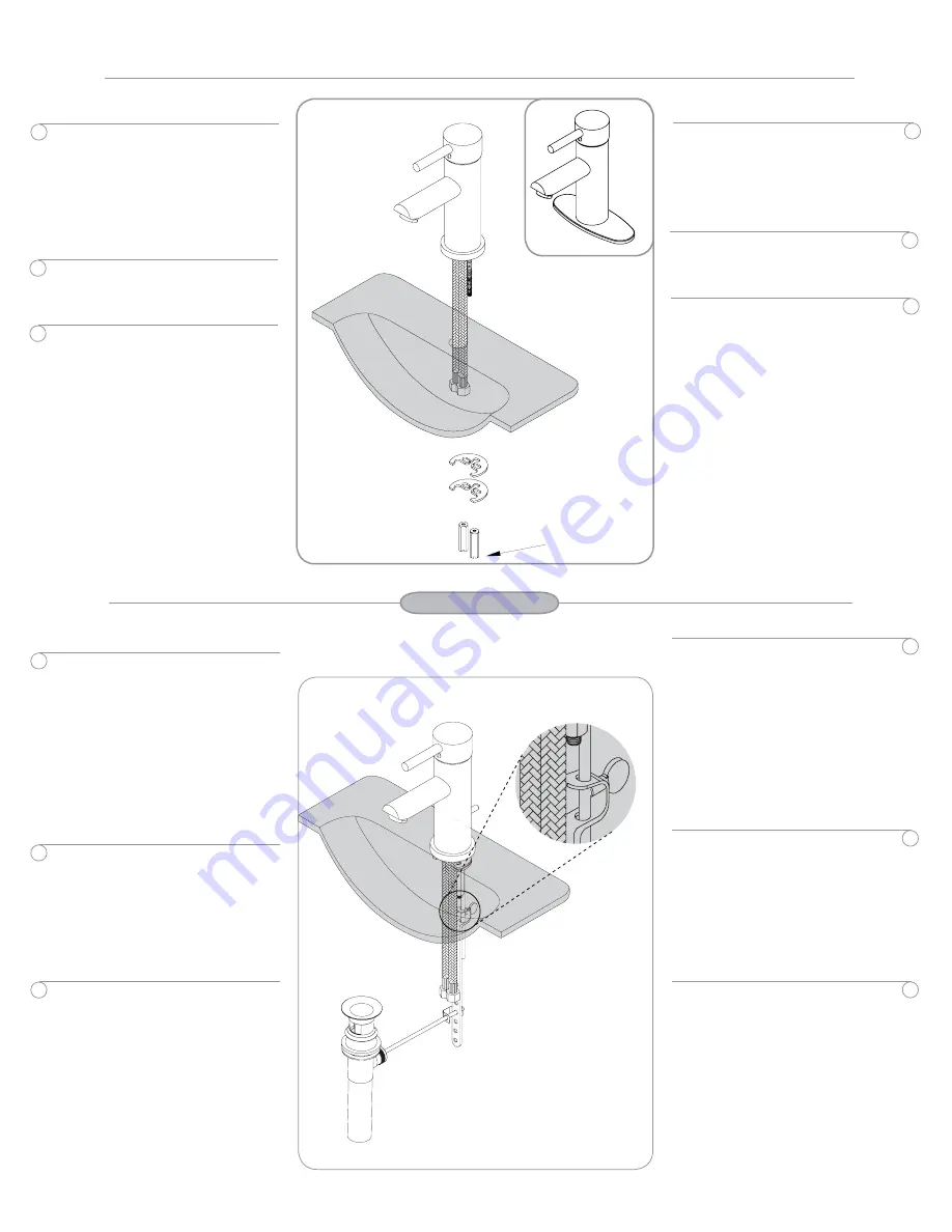
Installation du robinet
Placer la plaque de recouvrement (ill. A)
ou l’ensemble de bride du robinet
(ill. B), selon le cas, sur le ou les trous
du lavabo ou du comptoir. Insérer les
raccords flexibles tressés à travers le
trou central. Appliquez du mastic pour
plombier sous la sous-plaque
de plastique pour rendre votre
installation étanche.
Sous le lavabo ou le comptoir, placer la
rondelle de métal en U ainsi qu’un écrou
sur chaque boulon d’ancrage et serrer à
la main.
Aligner ensuite le robinet sur le dessus
du lavabo ou du comptoir. Serrer les
écrous doucement avec un tournevis
plat ou un outil approprié en prenant
soin de ne pas trop serrer.
Faucet installation
Place the cover plate (ill. A) or the base
flange kit (ill. B) on the hole(s) of the
lavatory sink or countertop, depending
on chosen installation. Insert the braided
flex connectors through the center hole.
Apply plumber putty under the plastic
cover deck plate to seal your installation.
Underneath the lavatory sink or counter,
place metal washer and locknut on each
threaded stud and tighten gently by
hand.
Now, position and properly align the
faucet on top of the lavatory sink or
countertop. Tighten the locknuts with a
flat head screwdriver or appropriate tool.
Do not overtighten.
1
1
3
3
1
2
3
1
2
3
Étape 2
Step 2
Installation de la bonde d’évacuation
mécanique
Enlever le bouchon. Dévisser le collet
afin de le séparer du corps de la bonde.
Appliquer du mastic de plombier au dos
du collet ou l’anneau de caoutchouc
(si inclus). Ne pas utiliser le mastic et
l’anneau combinés. Insérer le corps
de la bonde sous le comptoir, dans le
trou du lavabo, en dirigeant l’ouverture
pour la tige horizontale vers l’arrière.
Par dessus le lavabo, insérer le collet
dans le trou afin de le fixer au corps
de la bonde. Serrer fermement le
contre-écrou en dessous du lavabo.
Insérer le bouchon dans la bonde.
Dévisser l’écrou de l’ouverture pour
la tige. Insérer l’extrémité de la tige
horizontale (extrémité la plus près de la
boule) dans l’ouverture et vous assurer
qu’elle pénètre l’anneau du bouchon.
Retirer l’attache de retenue. Insérer
l’écrou puis serrer par dessus la boule
de la tige afin de la fixer en place.
Insérer la tirette de la bonde dans la
courroie ajustable sans serrer la vis.
Attacher la courroie à la tige horizontale
de la bonde d’évacuation mécanique
à l’aide de l’attache de retenue. Avec
la tige horizontale en position ouverte
(c-à-d bouchon relevé), ajuster la tirette
pour qu’elle arrive au bas de la fente
au dos du robinet. Laisser un espace
de 2 po entre le bas des boulons
de retenue et le haut de la courroie
pour vous assurer de l’étanchéité du
bouchon. Resserrer la vis de la courroie
fermement (ill. A).
Mechanical P.O. plug installation
Take off the stopper cap. Unscrew
flange to separate it from the body
of the mechanical P.O. plug. Apply
plumber’s putty or the rubber ring (if
included) to underside of the flange.
Do not use the putty and rubber ring
together. From underneath the lavatory
sink, insert the body of the P.O. plug
ensuring that the opening of the
horizontal rod is to the back. From over
the sink, insert the flange to secure it
to the body of the P.O. plug. Tighten the
lock nut underneath the sink.
Insert stopper cap in the P.O. plug top
opening. Unscrew the lock nut installed
on the opening of the horizontal rod.
Insert the end of the horizontal rod (end
closest to the ball) in the opening. Make
sure that the rod passes through the
hole at the bottom of the stopper cap.
Take off the retainer clip, insert the lock
nut and tighten it over the ball of the rod
to secure it in place.
Insert the lift rod through the top hole of
the adjustable strap without tightening
the screw. Attach strap to horizontal
rod of the P.O. plug with the retainer
clip. With the horizontal rod in the open
position (stopper cap is raised), position
the lift rod at the bottom of the opening
behind the faucet. Make sure to leave
a 2” clearance between the bottom
of the anchor rods and the top of the
ajustable strap to ensure that the
stopper cap close properly. Tighten strap
screw (ill. A).
5125POCP - 5125POBN
ill. A


