2.2 INSTALLATION SITE
Failure to install dryer in the proper ambient conditions will affect the dryer’s ability to condense refrigerant gas.
This can cause higher loads on the compressor, loss of dryer efficiency and performance, overheated condenser
fan motors, electrical component failure and dryer failure due to the following: compressor loss, fan motor failure
and electrical component failure. Failures of this type will affect warranty considerations.
Do not install dryer in an environment of corrosive chemicals, explosive gasses, poisonous gasses, steam heat,
areas of high ambient conditions or extreme dust and dirt.
In case of fire, use an approved fire extinguisher,
w
ater is not an acceptable means in cases of electrical fire.
Minimal installation requirements:
•
Select a clean, dry room, free from dust, and protected from atmospheric disturbances.
•
The supporting plate must be smooth, horizontal and able to hold the weight of the dryer.
•
Minimum ambient temperatures 34°F see the data plate for maximum temperature.
•
Allow at least 16 inches of clearance on each side of the dryer for proper ventilation and to facilitate
maintenance operations.
The dryer doesn't require to be fixed to the supporting surface. Locks will be required for special installations
(on brackets, hanging, etc.).
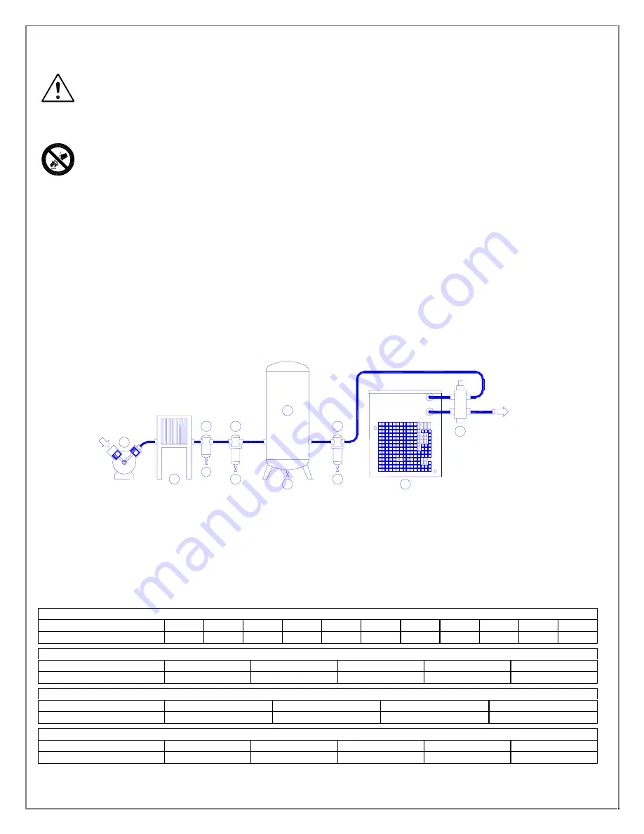
2.3 INSTALLATION LAYOUT
1
Air compressor
6
Final filter
2
Aftercooler
7
Dryer
3
Condensate separator
8
By-pass group (optional)
4
Pre-Filter
9
Condensate drain
5
Compressed air receiver
Correction factor for inlet air pressure changes:
Inlet air pressure
psig
60
70
85
100
115
130
140
155
170
200
232
Factor
0.70
0.85
0.93
1.00
1.06
1.11
1.15
1.18
1.21
1.25
1.28
Correction factor for ambient temperature changes:
Ambient temperature
ºF
80
90
100
110
115
Factor
1.09
1.06
1.00
0.90
0.83
Correction factor for inlet air temperature changes:
Air temperature
ºF
90
100
110
115
Factor
1.15
1.00
0.82
0.75
Correction factor for DewPoint changes:
DewPoint ºF
38
40
44
47
50
Factor
1.00
1.05
1.10
1.15
1.20
2
1
9
9
3
4
8
7
9
9
6
5
OUT
IN


