5
Tone
Number
Switch
Settings
1 2 3 4 5 6
Second
Stage
Alarm
Third
Stage
alarm
Tone 1
Tone 2
Tone 3
Tone 4
Tone 5
Tone 6
Tone 7
Tone 8
Tone 9
Tone 10
Tone 11
Tone 12
Tone 13
Tone 14
Tone 15
Tone 16
Tone 17
Tone 18
Tone 19
Tone 20
Tone 21
Tone 22
Tone 23
Tone 24
Tone 25
Tone 26
Tone 27
Tone 28
Tone 29
Tone 30
Tone 31
Tone 32
Tone 33
Tone 34
Tone 35
Tone 36
Tone 37
Tone 38
Tone 39
Tone 40
Tone 41
Tone 42
Tone 43
Tone 44
Tone 45
Tone 46
Tone 47
Tone 48
Tone 49
Continuous 340Hz
Alternating 800/1000Hz @ 0.25s intervals
Slow whoop 500/1200Hz @ 0.3Hz with 0.5s gap repeated
Sweeping 500/1000Hz @ 1Hz
Continuous 2400Hz
Sweeping 2400/2900Hz @ 7Hz
Sweeping 2400/2900Hz @ 1Hz
Siren 500/1200/500Hz @ 0.3Hz
Sawtooth 1200/500Hz @ 1Hz -
D.I.N.
Alternating 2400/2900Hz @ 2Hz
Intermittent 1000Hz @ 1Hz
Alternating 800/1000Hz @ 0.875Hz
Intermittent 2400Hz @ 1Hz
Intermittent 800Hz 0.25s ON, 1s OFF
Continuous 800Hz
Intermittent 660Hz 150Ns ON, 150ms OFF
Alternating 544Hz (100ms) / 440Hz (400ms) –
NFS 32-001
Intermittent 660Hz 1.8s ON, 1.8s OFF
Sweep 1400Hz to1600Hz up 1s 1600Hz to 1400Hz down 0.5s
Continuous 660Hz
Alternating 554/440Hz @ 1Hz
Intermittent 544Hz @ 0.875Hz
Intermittent 800Hz @ 2Hz
Sweeping 800/1000Hz @ 50Hz
Sweeping 2400/2900Hz @ 50Hz
Simulated bell
Continuous 554Hz
Continuous 440Hz
Sweeping 800/1000Hz @ 7Hz
Continuous 300Hz
Sweeping 660/1200 @ 1Hz
Two Tone Chime
Intermittent 745Hz
Alternating 1000/2000Hz @ 0.5s –
Singapore
420Hz @ 0.625s -
Australian Alert
500-1200Hz 3.75s / 0.25s -
Australian Evacuate
Continuous 1000Hz
Continuous 2000Hz
Intermittent 800Hz 0.25s ON 1s OFF
Alternating 544Hz (100ms) / 440Hz (400ms) –
NFS 32-001
Motor Siren – Slow rise to 1200Hz
Motor Siren – Slow rise to 800Hz
Continuous 1200Hz
Motor Siren – Slow rise to 2400Hz
Intermittent 1000Hz 1s ON, 1s OFF
Sawtooth 1200/500Hz @ 1Hz -
D.I.N.
(PFEER P.T.A.P)
Intermittent 1000Hz 1s ON, 1s OFF –
PFEER General Alarm
420Hz @ 0.625s -
Australian Alert
500-1200Hz 3.75s / 0.25s -
Australian Evacuate
0 0 0 0 0 0
1 0 0 0 0 0
0 1 0 0 0 0
1 1 0 0 0 0
0 0 1 0 0 0
1 0 1 0 0 0
0 1 1 0 0 0
1 1 1 0 0 0
0 0 0 1 0 0
1 0 0 1 0 0
0 1 0 1 0 0
1 1 0 1 0 0
0 0 1 1 0 0
1 0 1 1 0 0
0 1 1 1 0 0
1 1 1 1 0 0
0 0 0 0 1 0
1 0 0 0 1 0
0 1 0 0 1 0
1 1 0 0 1 0
0 0 1 0 1 0
1 0 1 0 1 0
0 1 1 0 1 0
1 1 1 0 1 0
0 0 0 1 1 0
1 0 0 1 1 0
0 1 0 1 1 0
1 1 0 1 1 0
0 0 1 1 1 0
1 0 1 1 1 0
0 1 1 1 1 0
1 1 1 1 1 0
0 0 0 0 0 1
1 0 0 0 0 1
0 1 0 0 0 1
1 1 0 0 0 1
0 0 1 0 0 1
1 0 1 0 0 1
0 1 1 0 0 1
1 1 1 0 0 1
0 0 0 1 0 1
1 0 0 1 0 1
0 1 0 1 0 1
1 1 0 1 0 1
0 0 1 1 0 1
1 0 1 1 0 1
0 1 1 1 0 1
1 1 1 1 0 1
0 0 0 0 1 1
Tone 2
Tone 17
Tone 2
Tone 6
Tone 3
Tone 7
Tone 10
Tone 2
Tone 15
Tone 7
Tone 2
Tone 4
Tone 15
Tone 4
Tone 2
Tone 18
Tone 2
Tone 2
Tone 2
Tone 2
Tone 2
Tone 2
Tone 6
Tone 29
Tone 29
Tone 2
Tone 26
Tone 2
Tone 7
Tone 2
Tone 26
Tone 26
Tone 2
Tone 38
Tone 36
Tone 35
Tone 9
Tone 34
Tone 23
Tone 31
Tone 2
Tone 2
Tone 2
Tone 2
Tone 38
Tone 47
Tone 46
Tone 49
Tone 26
Tone 5
Tone 5
Tone 5
Tone 5
Tone 20
Tone 5
Tone 5
Tone 5
Tone 2
Tone 5
Tone 5
Tone 5
Tone 5
Tone 5
Tone 5
Tone 5
Tone 27
Tone 5
Tone 5
Tone 5
Tone 5
Tone 5
Tone 5
Tone 5
Tone 5
Tone 15
Tone 5
Tone 5
Tone 5
Tone 5
Tone 5
Tone 15
Tone 5
Tone 45
Tone 5
Tone 5
Tone 45
Tone 45
Tone 17
Tone 27
Tone 5
Tone 5
Tone 5
Tone 5
Tone 34
Tone 37
Tone 37
Tone 5
Tone 37
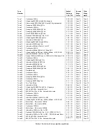
Table 1 Function of tone selection switches


