


13
6.3.5.2 Alarm activation
Fieldbus variables that have not been validated
are displayed with dark characters on a light
background, and some screen formats also
contain a status indication. This sub-menu allows
the alarm outputs to be conditioned so that they
only operate with validated fieldbus data, or to
operate irrespective of data validity.
6.3.5.3 Alarm output
There is a separate sub-menu for each of the six
alarm outputs; these link the alarm to one of the
displayed fieldbus variables and define the alarm
function and the setpoints.
To link the alarm to a displayed variable, position
the cursor over the ‘IN_n’ field, press
P
and using
the
Up
or
Down
button select the required input
source. Enter the selection by pressing the
E
button.
Each alarm output can be N/O or N/C in the non-
alarm condition. To change the setting, position
the highlight over the ‘N/O’ or ‘N/C’ field, press
P
and use the
Up
or
Down
button to toggle the
setting. Enter the selection by pressing the
E
button.
Each alarm has three functions that can be
independently enabled to condition the output as
a low or high alarm, or as a combined low and
high alarm, either with or without hysteresis.
The required functions can be individually enabled
by positioning the highlight over the Enb/Dis
(Enabled/Disabled) column, pressing
P
and
toggling the function to the required state, then
entering the selection by pressing the
E
button.
Alarm setpoints are entered digit by digit. Place
the highlight over the setpoint to be adjusted and
press
P;
the flashing digit to be adjusted may then
be selected by again pressing
P
. When all the
digits have been adjusted, operating the
E
button
enters the value and moves the menu up one
level.
The function of all alarms may be reviewed from
the alarm summary menu - see 6.3.5.1.
6.3.6 Display
6.3.6.1 Settings
The backlight brilliance and display contrast are
adjustable from this sub-menu.
6.3.6.2 Quick Access
This sub-menu enables the Quick Access Menu
which is described in sections 2.1 & 6.4 When
enabled, an operator can adjust the display
contrast and backlight brilliance without having
access to any other conditioning menus.
6.3.6.3 Access Code
Defines a four digit alphanumeric code that must
be entered to gain access to the Quick Access
Menu. Alpha characters are case sensitive.
Default code 0000 allows direct access without a
code.
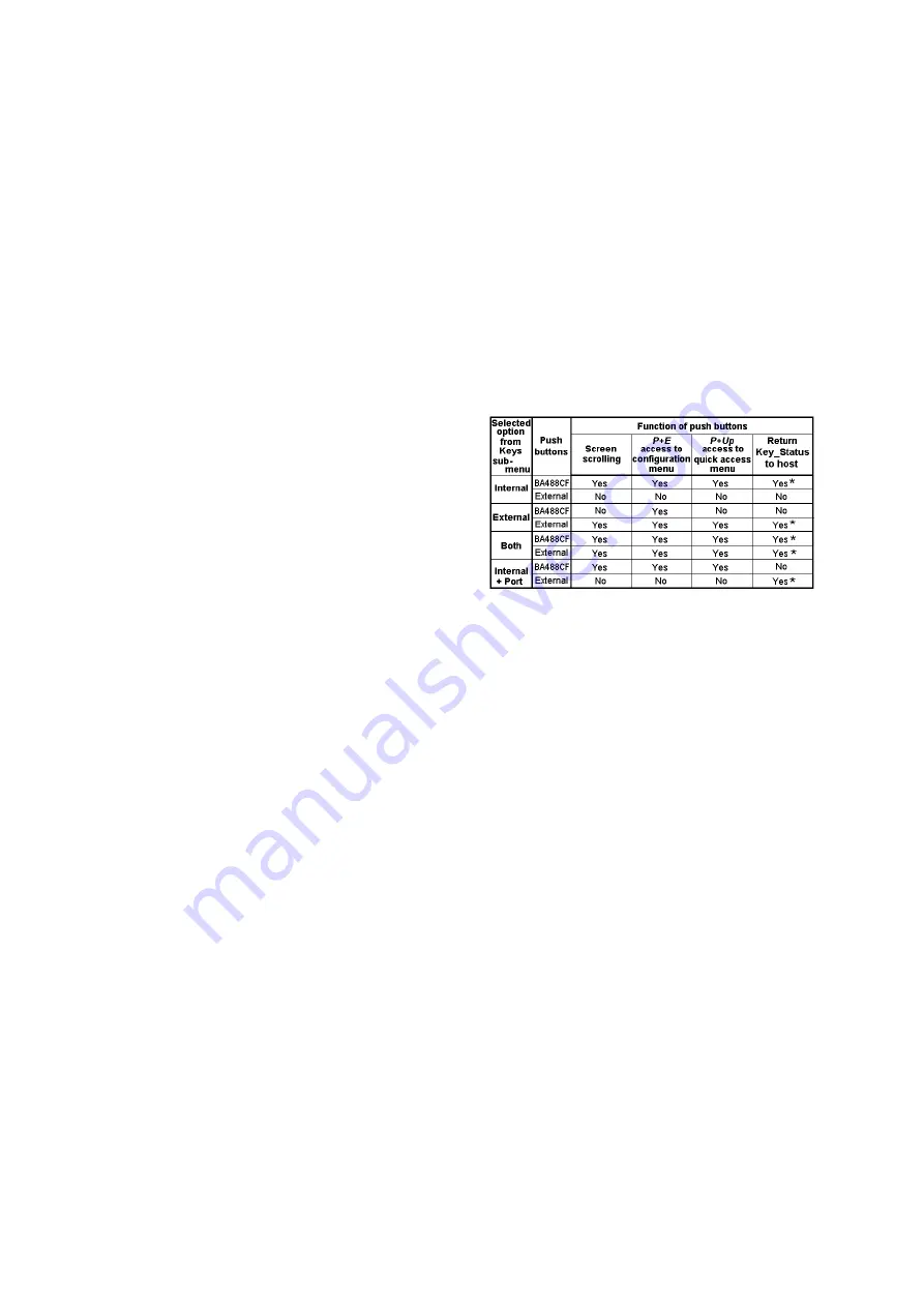
6.3.7 Keys
The function of the front panel push buttons may
be transferred to the six optional external push
buttons, with or without disabling the BA488CF
front panel push buttons. The table below shows
the function of the BA488CF front panel and the
external push buttons for each of the four options
that may be selected in the Keys sub-menu.
* Apart from when ‘IPort’ is selected, the Key_Status
does not function when the instrument is in the configuration
menu.
The fourth option, ‘In Port’ allows the front
panel push buttons to be used for controlling the
BA488CF Fieldbus Display and the optional
external push buttons to independently enter
operator acknowledgements or controls. This
option also allows the status of plant mechanical
switches to be returned to the host.
For applications where the instrument is only
displaying 1, 2, 3 or 4 variables on a single
screen, it is recommended that external buttons
are selected but not fitted. This will disable the
instrument front panel buttons, but still provide
access to the configuration menu, which may be
protected by a security code.
6.3.8 Code
Defines the four digit alphanumeric code that must
be entered to gain access to the instrument
configuration menus. Alpha characters are case
sensitive. Default code 0000 allows direct access
without a code.
6.3.9 Unit Info
Displays the instrument model number and the
firmware version.


