background image

21

9.3.11  Access Setpoint:  AcSP

This function controls a separate menu which
provides direct access to the alarm setpoints when
the indicator is in the display mode.  See section
9.3.12 for a full description.    An operator may
therefore adjust the alarm setpoints without having
access to the programme and alarm menus.
Further protection is provided by a separate
security code.

This direct access menu is enabled and a separate
security code entered from the 'AcSP' function in
the programme menu as shown in Fig 11.  To
change the menu parameters select 'AcSP' from
the programme menu and press P  which will
display the enable prompt 'EnbL'.  Press P again to
reveal if the direct access menu is 'On' or 'OFF'.
The  Up or Down buttons will toggle the display
between the two conditions.

If 'OFF' is selected, the operator will not have
access to the setpoints from the display mode.
Return to the 'AcSP' prompt in the main menu by
pressing E twice.

If 'On' is selected, the operator will have direct
access to the alarm setpoints from the display
mode via a separate optional security code.   To
define the four digit numerical code press P to
return to the 'Enbl' prompt followed by the Up or
Down button to select the access code prompt
'AcCd'.   Pressing will reveal the current security
code.  Each digit of the code may be changed by
operating the Up and Down push-buttons, and the
P button to move to the next digit.  When the
required code has been entered, press E twice to
return to the 'AcSP' prompt in the Programme
Menu.

Code 0000 will disable the security code allowing
direct access to the setpoints by pressing the  P
and  Up buttons simultaneously.  New instruments
with alarms are supplied with this function disabled
and the security code set to 0000

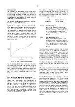
9.3.12  Adjusting alarm setpoints from the
            display mode

Access to the alarm setpoints from the indicator
display mode is obtained by operating the P and
Up push-buttons simultaneously as shown in Fig
12.  If the setpoints are not protected by a security
code the alarm setpoint  prompt 'SP1' will be
displayed.  If the setpoints are protected by a
security code, 'COde' will be displayed first.
Pressing  P again will enable the alarm security
code to be entered digit by digit using the Up and
Down buttons to change the flashing digit, and the
P push-button to move to the next digit.  If the
correct code is entered pressing E will cause alarm
setpoint prompt 'SP1' to be displayed.  Pressing
the  Up or Down button will toggle the display

between the two alarm setpoint prompts 'SP1' and
'SP2'.

If an incorrect security code is entered, or a button
is not pressed within ten seconds, the indicator will
automatically return to the display mode.

Fig 12 Setpoint adjustment from the display mode

To adjust an alarm setpoint select 'SP1' or 'SP2'
and press  P which will reveal the current setting.
Each digit of the setpoint may be adjusted using
the Up and Down push-buttons, and the  P button
to move to the next digit.  When the required
setpoint has been entered, pressing E  will return
the display to the 'SP1' or 'SP2' prompt from which
the other setpoint may be selected, or the indicator
may be returned to the display mode by pressing E
again.

Direct access to the alarm setpoints is only
available when the 


menu is enabled - see section

9.3.11

Summary of Contents for BA327C

Page 1: ...BA327C BA328C intrinsically safe loop powered 4 digit panel mounting indicators issue 11 Issue 11 3rd November 2009...

Page 2: ...rator 8 Maintenance 8 1 Fault finding during commissioning 8 2 Fault finding after commissioning 8 3 Servicing 8 4 Routine maintenance 8 5 Guarantee 8 6 Customer comments 9 Accessories 9 1 Scale card...

Page 3: ...lt conditions the voltage current and power at the input terminals of each instrument will not exceed those specified for simple apparatus in Clause 5 4 of EN50020 1994 The BA327C and BA328C are also...

Page 4: ...allations in Switzerland This manuals describes installations which conform with EN60079 Part 14 When designing systems for installation outside the UK th local Code of Practice should be consulted 3...

Page 5: ...s BEKA associates name and location Non European certification information may also be shown 4 SYSTEM DESIGN FOR HAZARDOUS AREAS 4 1 Transmitter loops BA327C and BA328C indicators may be connected in...

Page 6: ...iers a two channel Zener barrier or a galvanic isolator must be used Again it is necessary to ensure that the voltage capability of the 4 20mA signal is sufficient to drive the indicator plus the volt...

Page 7: ...erall dimensions of each instrument and the required panel cut out dimensions To achieve an IP65 seal between the instrument enclosure and the instrument panel the smaller tolerance aperture must be u...

Page 8: ...3 EMC The BA327C and BA328C comply with the requirements of the European EMC Directive 2004 108 EEC For specified immunity all wiring should be in screened twisted pairs with the screens earthed with...

Page 9: ...ating decimal points for a few seconds while the new information is stored in non volatile memory All new BA327C and BA328C indicators are supplied calibrated as requested at the time of ordering If c...

Page 10: ...10...

Page 11: ...lowing table shows the output current from a non linearised differential flowmeter of full flow Current output mA 2 5 4 01 10 0 4 16 25 0 5 00 50 0 8 00 75 0 13 00 100 0 20 00 6 3 Resolution rESn This...

Page 12: ...orrect pressing P will transfer control to the next digit When the least significant digit has beenadjusted press E to return to the SPAn prompt followed by E to return to the menu 6 7 Conditioning su...

Page 13: ...calibration and conditioning of the instrument may be protected by a four digit security code which must be entered before access to the programme menu is granted New instruments are programmed with...

Page 14: ...Down buttons select 50 and then press E twice to return to the main menu Step 5 Define function of P push button Select C P from the main menu and press P to reveal the function of the P button in the...

Page 15: ...to the main menu Step 4 Define function of P push button Select C P from the main menu and press P to reveal the function of the P button in the display mode Select 4 20 and return to the main menu by...

Page 16: ...ing correctly the following procedure should be followed Symptom Cause Solution No display No power Check that current 0V between supply is flowing in the loop terminals 1 and 3 Unstable 4 20mA input...

Page 17: ...ependently programmed as high or low alarms with normally open or normally closed outputs Fig 8 illustrates the conditions available and shows which are fail safe i e in the alarm condition the output...

Page 18: ...18...

Page 19: ...mmable alarm functions Display Description of function EnbL Alarm enable Enables or disables the alarm function without changing the alarm parameters See section 9 3 4 SP1 Alarm setpoint 1 Adjusts the...

Page 20: ...y pressing the Up or Down button followed by the E button to return to the alarm menu 9 3 8 Hysteresis HStr During programming hysteresis is shown in the units the indicator has been calibrated to dis...

Page 21: ...security code allowing direct access to the setpoints by pressing the P and Up buttons simultaneously New instruments with alarms are supplied with this function disabled and the security code set to...

Page 22: ...using the Add and dEL functions In both these functions the indicator initially displays the current break point and the total number of break points being used e g 5 13 current total number of break...

Page 23: ...f break points Each subsequent operation of the P push button will introduce an additional break point When adding a break point to a calibrated indicator the insertion position can be selected using...

Page 24: ...24...

Page 25: ...e output which enhances daylight viewing but an additional IS interface and field wiring are required 9 6 1 Separately powered backlight The separately powered backlight is segregated from the measuri...

Page 26: ...is loop powered This eliminates the need for a separate Zener barrier or galvanic isolator and associated wiring for the backlight thus significantly reducing the installation cost As shown in Fig 16...

Page 27: ...3 A1 2 4 20mA input in nonincendive circuit The BA327C and BA328C are also Factory Mutual approved as nonincendive for Class I Division 2 locations which allows both indicators to be installed in Div...

Page 28: ...between the backlight and the measuring circuits should be maintained by following the wiring methods recommended in ANSI NFPA70 article 504 See Fig 15 A1 3 2 2 Loop powered backlight This backlight h...

Page 29: ...29...

Page 30: ...30...

Page 31: ...31...

Page 32: ...f Conformity number IECEx ITS 05 0003 which specifies the following certification code and marking Ex ia IIC T5 Ta 40o C to 60 o C The specified intrinsic safety parameters are identical to the ATEX s...

Reviews: