background image

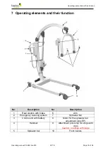
Operating elements and their function  


Operating manual CARLO Alu 230 

V2.7 E 

Page 19 of 56   

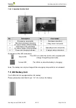
7.4.2  Canadian Control Unit 


No. 

Description 

No. 

Description 

Emergency stop switch 

Handset connection 

Electrical emergency lowering 

(in case of failure of the handset) 

Lifting motor connection 

Adjustment of the spreading 

(in case of failure of the handset) 

Spreading motor connection 

Power and charging indicator 

Charger cable connection 

 
Explanation of the LED-indications 


Green LED 

The LED is on when the control unit is supplied with 

voltage through the power cable. 


Yellow LED 

The LED is on when the battery is charging. 

 
Note: The battery can only be charged if the emergency stop switch is not actuated! 
 

7.5  24V-Battery Unit 

The CARLO ALU is equipped with a 24V-battery.  
Please proceed as described in par. 13.7.4 to remove the battery. 


Summary of Contents for CARLO Alu Classic 230

Page 1: ...CARLO Alu Classic 230 Comfort EP 230 Sling lift Version 2 7 E Subject to technical modifications 2019 08 20 Operating manual Original operating manual...

Page 2: ...ed and appropriate use 9 4 2 Other prescriptions 9 4 3 Safety instructions 9 4 4 List of used safety instructions 10 4 5 Warnings 11 5 Transport 13 5 1 Unpacking the product 13 5 1 1 Removing the card...

Page 3: ...patient resident 29 8 2 3 Putting the patient resident down 30 8 3 Digital scale SLS option 31 8 4 Maintenance and Care of the 24 Volt Battery 31 9 Cleaning Disinfection 31 9 1 Cleaning the Sling lift...

Page 4: ...of 56 13 7 Mounting instructions 44 13 7 1 Rear Castor Replacement 44 13 7 2 Front Castor Replacement 45 13 7 3 Control including Handle Mounting Plate and Battery Compartment 46 13 7 4 Replacing the...

Page 5: ...ured and tested according to stringent quality criteria 1 2 Manufacturer s address BEKA Hospitec GmbH Am R benmorgen 3 35582 Wetzlar Phone 49 0 641 9 22 22 0 Fax 49 0 641 9 22 22 20 info beka hospitec...

Page 6: ...ll as the national regulations laws and prescriptions related to work safety and accident prevention The manufacturer of the product is only responsible for the safety and the reliability of the produ...

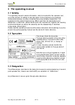
Page 7: ...al and the safety instructions before starting to use the product Keep the operating manual near the device for future reference 3 2 Type plate This image shows the type plate The type plate is situat...

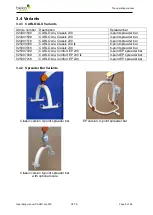
Page 8: ...Classic 230 4 point spreader bar 925003008 CARLO Alu Classic 230 IL 6 point spreader bar 925003018 CARLO Alu Classic 230 6 point spreader bar 925007000 CARLO Alu Comfort EP 230 4 point EP spreader bar...

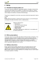
Page 9: ...fusion epileptic attacks may only be treated with the CARLO ALU in consultation with the attending physician 4 2 Other prescriptions The product meets the current VDE prescriptions 0100 and 0100 710 H...

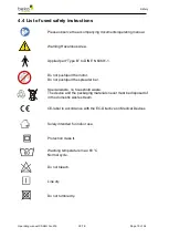
Page 10: ...DIN EN 60601 1 Do not push pull the motor Do not push pull the spreader bar Special waste no household waste The device and the packaging materials never must be disposed of in the domestic waste stre...

Page 11: ...caregiver is required throughout the treatment Make sure that the sling form and size match the resident s body Check prior to lifting that all clips or loops are correctly fixed to the spreader bar...

Page 12: ...Check the applied sling for visual damages prior to using it Move the CARLO ALU by means of the handles provided to that effect instead of pulling the spreader bar Never cover up oversticker or chang...

Page 13: ...rap with the cutter knife Remove the strap Lift the cardboard up to remove it and put it aside 5 1 2 Loosening the product from the pallet The product is on both sides strapped to the pallet Proceed i...

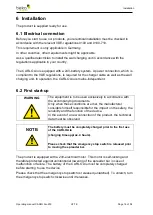
Page 14: ...start up WARNING The equipment is to be used exclusively in accordance with the accompanying documents Only when these conditions are met the manufacturer considers himself responsible for the impact...

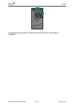
Page 15: ...Installation Operating manual CARLO Alu 230 V2 7 E Page 15 of 56 The emergency stop switch is released by turning the button to the right i e clockwise...

Page 16: ...their function No Description No Description 1 Rear castors with brake 6 Arm 2 Emergency lowering system 7 Spreader bar 3 Control unit with battery 8 Motor for the spreader bar adjustment only EP 4 H...

Page 17: ...on No Description 1 Arm 3 Scale optionally available 2 Attachment points for slings with loops Caution no slings with clips 7 2 Handset No Description No Description 1 Overload 4 Only EP spreader bar...

Page 18: ...an 25 When you push a button an audible signal will be emitted Service indication orange LED flashes Please have your stand up and raising aid checked Orange LED overload max weight of 230 kg exceeded...

Page 19: ...in case of failure of the handset 7 Spreading motor connection 4 Power and charging indicator 8 Charger cable connection Explanation of the LED indications Green LED The LED is on when the control uni...

Page 20: ...required power cable is included in the delivery The charging time for the battery units is approx 4 hours No Description No Description 1 Mains input socket 3 Charging indicator yellow LED 2 Mains o...

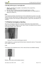
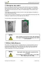
Page 21: ...uld cause the emergency lowering mechanism to run too smoothly In case of a failure of the emergency lowering system a reset at the manufacturer s is required 7 8 Electrical emergency lowering Should...

Page 22: ...ALU sling hoist thus making any unauthorized use of the sling hoist more difficult Turn the button in the direction of the arrow to unlock NOTE In the Canadian version of the control unit the battery...

Page 23: ...necessary be washed in accordance with the manual This is prescribed in particular to reduce the risk of infections to an absolute minimum in the event that the same equipment is used for other resid...

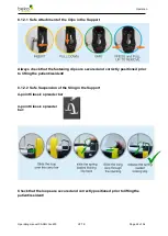
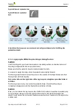
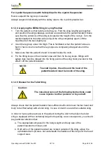
Page 24: ...ways check that the fastening clips are secured and correctly positioned prior to lifting the patient resident 8 1 2 2 Safe Suspension of the Sling in the Support 4 point Classic spreader bar 4 point...

Page 25: ...to apply the sling when the patient leans slightly forward Pull the leg loops forward so that they are on the outside of the thigh Make sure that the leg loops protrude equally Pull on the left and t...

Page 26: ...the lifting loops in the shoulder area and then fix the leg loops Slings with safety clips must be clipped into the fixing points of the sling hoist provided to this effect Lift the patient resident N...

Page 27: ...plied Make sure that the patient s resident s arms are located outside of the sling and over the upholstered arm pit area Always make sure that the patient resident is in an upright sitting position w...

Page 28: ...n the highest possible position is reached the upward movement is automatically stopped Keep the button of the handset pressed to lower the spreader bar The spreader bar is lowered Release the button...

Page 29: ...ward and lift one leg at the time Bring the leg loops under the patient s resident s leg Check that the shoulders and the head of the patient resident are correctly positioned in the sling Particularl...

Page 30: ...of the wheelchair if required 5 Lower the lifting arm with the spreader bar until the patient resident sits safely in the chairs or lies safely on the bed and the loops of the sling are relieved 6 Rem...

Page 31: ...arge may destroy the battery The battery s lifetime basically depends on the charge number of lifting cycles and the charging state It can be up to 5 years Have defective or worn out batteries and def...

Page 32: ...rs and the patients BEKA Hospitec prescribes an annual safety check The execution of the safety checks and maintenance must be documented and proven on request Please use your inventory register to th...

Page 33: ...he proper functioning of the handset up down spreading spreader bar inclination Check the emergency lowering system Check the smooth running of the castors Check the slings for damages Check the state...

Page 34: ...ame motor does not run a Check if the emergency stop switch is released or pressed b Check that the control box is correctly plugged in c Check the battery The drive stops during the lifting procedure...

Page 35: ...eck for damage Problems with the Battery Remedy The battery is placed correctly but the indicator lights are not lit Inform the after sales service The indicator light does not go out after multiple h...

Page 36: ...ant Safe Working Load SWL max 230 kg Turning radius 147 5 cm Electrical data Power Supply 24 Volt Battery max Power consumption 10A 240VA applied Part Type B Duration of treatment 10 2 min continuous...

Page 37: ...ax 400 mA Fuse T1 25 A 250V Protection class IPX 5 Battery battery type Lead acid battery Power Output 24 V DC capacity 2 9 Ah Output current Iout max 10A Protection class IPX 5 Additive for control b...

Page 38: ...Alu 230 V2 7 E Page 38 of 56 13 2 Dimensions CARLO ALU Classic EP Note Depending on the hanger bar used and the use of the optionally available scale the distance from the floor to the sling suspensi...

Page 39: ...Appendix Operating manual CARLO Alu 230 V2 7 E Page 39 of 56 13 3 Declaration of Conformity...

Page 40: ...ansfer sling Size XXL 923003500 Bathing sling Size S 923004100 Bathing sling Size M 923004200 Bathing sling Size L 923004300 Bathing sling Size XL 923004400 Bathing sling Size XXL 923004500 Nylon toil...

Page 41: ...ze S M L XL XXL Weight 35 65 kg 55 85 kg 75 125 kg 120 160 kg 160 210 kg Color red yellow green blue orange Toilet sling with loops Description Guideline for sling sizes made of nylon washable at max...

Page 42: ...05417 Nylon sling for double leg amputees Size XXL 922005517 Slings with clips US Canada Slings with clips Description Art N Nylon transfer sling Size S 922005103 Nylon transfer sling Size M 922005203...

Page 43: ...ze XXL 922005517 Transfer sling with clips Description Guidelines for sling sizes made of nylon washable at max 60 C Size S M L XL XXL Weight 35 65 kg 55 85 kg 75 125 kg 120 160 kg 160 210 kg Color re...

Page 44: ...Rear Castor Replacement Image 1 Required tools 1 x 10 mm Allen wrench Image 2 Additional parts tools 1 x rear castor Order number S9200130 1 x thread lock fluid medium tight Image 3 Put an object e g...

Page 45: ...s tools 1 x front castor Order number S9200350 1 x thread lock fluid medium tight Image 3 Put an object e g wooden block under the side where you want to replace the castor to free the castor Image 4...

Page 46: ...t Image 4 Unscrew and remove the left hand screw of the handle in the mounting plate Image 5 Unscrew and remove the right hand screw of the handle in the mounting plate Image 6 The image shows the mou...

Page 47: ...of the control box and remove the control box Image 16 Unscrew and remove the top locking screw from the battery compartment Image 17 Unscrew and remove the middle locking screw from the battery compa...

Page 48: ...ge 1 The image shows the inserted battery Image 2 Unlock the battery by means of the release lever in the battery handle Image 3 You can lift the battery up to remove it Image 4 The image shows the re...

Page 49: ...after listed ELECTROMAGNETIC ENVIRONMENTS The customer or the user of the product must ensure that the appliance is used in such environment Emission measurements Compliance Electromagnetic environmen...

Page 50: ...y of the supply voltage should match that of a typical business or hospital environment Overvoltage IEC 61000 4 5 1 kV cable against cable 2 kV cable against ground connection 1 kV cable against cable...

Page 51: ...h of fixed HF transmitters as determined by an electromagnetic field survey a should be less than the COMPLIANCE LEVEL in each frequency range b In the vicinity of equipment marked with the following...

Page 52: ...pending on the transmitting frequency in m 150 kHz to 800 MHz d 0 35 P 80 MHz to 800 MHz d 1 2 P 800 MHz to 2 5 GHz d 2 3 P 0 01 0 1 1 10 100 0 04 0 11 0 35 1 1 3 5 0 12 0 38 1 2 3 8 12 0 23 0 73 2 3...

Page 53: ...mber _____________________________________________ Date of purchase _____________________________________________ Site _____________________________________________ Checks and inspection conducted upo...

Page 54: ...Appendix Operating manual CARLO Alu 230 V2 7 E Page 54 of 56 Type of inspection Date Result Measure Signature...

Page 55: ...Appendix Operating manual CARLO Alu 230 V2 7 E Page 55 of 56 Your notes...

Page 56: ...BEKA Hospitec GmbH Am R benmorgen 3 35582 Wetzlar Germany Phone Fax 49 0 6 41 9 22 20 0 V2 7 E ge ndert 26 08 2019 MH Warnhinweis Bremsen sollen ungebremst sein...

Reviews: