


4
FEEDBACK DESTROYER PRO FBQ2496 User Manual
5
FEEDBACK DESTROYER PRO FBQ2496 User Manual
1. Introduction
The FBQ2496 is the fastest (>0.2 sec.) and the only 96 kHz Feedback Suppressor
in this market price segment. Using an ultra-fast feedback detection algorithm,
it automatically and “intelligently” locates up to 20 feedback frequencies per
channel and sets extremely narrow notch fi lters to “destroy” them, leaving the
remainder of the signal virtually untouched.
Easy does it: with the “Set-and-Forget” default setting plus the Panic button,
your FEEDBACK DESTROYER can be up and running in no time! The auto mode
continuously monitors the mix, resetting programmed fi lters automatically,
while the manual mode allows individual setting of up to 40 fully parametric
fi lters with frequency, bandwidth and gain adjustment. Open MIDI architecture
means that future software updates and fl exible communication with digital
equipment are a no-brainer. With its various modes you can master just about
any live sound situation or use it as a creative sound-shaping tool.
1.1 Before you get started
1.1.1 Shipment
Your FBQ2496 was carefully packed at the assembly plant to assure secure
transport. Should the condition of the cardboard box suggest that damage may
have taken place, please inspect the unit immediately and look for physical
indications of damage.
◊
◊
Damaged equipment should NEVER be sent directly to us. Please inform
the dealer from whom you acquired the unit immediately as well
as the transportation company from which you took delivery.
Otherwise, all claims for replacement/repair may be rendered invalid.
◊
◊
Please always use the original packaging to avoid damage due to
storage or shipping.
◊
◊
Never let unsupervised children play with the FBQ2496 or with
its packaging.
◊
◊
Please dispose of all packaging materials in an environmentally
friendly fashion.
1.1.2 Initial operation
Be sure that there is enough space around the unit for cooling. To avoid overheating,
do not place the FBQ2496 on top of power amps or near radiators, etc.
◊
◊
Blown fuses must be replaced by fuses of the same type and rating.
Please refer to the “SPECIFICATIONS” for further details.
The mains connection is made using the enclosed power cord and a standard IEC
receptacle. It meets all international safety certifi cation requirements.
◊
◊
Please make sure that all equipment is properly grounded at all times.
For your own safety, never remove or disable the ground conductor of
the unit or of the AC power cord.
1.1.3 Online registration
Please register your new BEHRINGER equipment right after your purchase
by visiting http://behringer.com and read the terms and conditions of our
warranty carefully.
Should your BEHRINGER product malfunction, it is our intention to have it
repaired as quickly as possible. To arrange for warranty service, please contact
the BEHRINGER retailer from whom the equipment was purchased. Should your
BEHRINGER dealer not be located in your vicinity, you may directly contact
one of our subsidiaries. Corresponding contact information is included in the
original equipment packaging (Global Contact Information/European Contact
Information). Should your country not be listed, please contact the distributor
nearest you. A list of distributors can be found in the support area of our website
(http://behringer.com).
Registering your purchase and equipment with us helps us process your repair
claims more quickly and effi ciently.
Thank you for your cooperation!
2. What Causes Feedback?
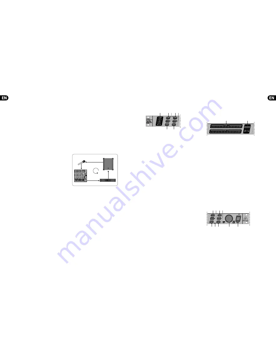
EUROLIVE B1220
EUROPOWER EP1500
UB2442FX-PRO
Fig. 2.1: How a feedback loop is created
A feedback loop is created when a microphone signal is fi rst reproduced on an
amplifi er, and is then picked up again by the same microphone (with the same
phasing). Then, it is amplifi ed and reproduced again. This feedback loop may,
under certain circumstances, keep on occurring and could escalate out of control.
With P.A. applications, there are two major types of setups in which feedback
can occur:
•
•
Front mix (also called F.O.H. = “front of house”) refers to the mix being
created when a signal from a mixing console is amplifi ed by one or more
power amplifi ers and is fed into loudspeakers facing the audience.
•
•
Monitor mix refers to the mix that also originates in the mixing console but
ends up driving one or more stage monitors. Unlike FOH speakers, a stage
monitor makes the music program audible to individual musicians.
◊
◊
Please bear in mind that high volume levels can damage both your
hearing and your equipment. Be sure to always select an appropriate
volume level.
3. Control Elements
and Connections
3.1 The front
(1)
(4)
(2)
(5)
(3)
(6)
(7)
Fig. 3.1: Control elements on FBQ2496’s left side
(1)
LEVEL METER
The LEVEL METER lets you monitor the input level. Eight LEDs are available
per channel. If the Clip LED lights up, digital distortion may occur on
FBQ2496’s input. In this case, reduce the input level.
(2)
LEARN
button
A quick tap on the LEARN button (LED lights up) gets you into the LEARN
mode. The FBQ2496 will immediately start looking for critical frequencies
and will deploy as many Single-Shot fi lters as necessary (of course, music or
noise has to be present in the room for this to work). Besides, using the
wheel
(17)
, you can manually determine the number of Single-Shot fi lters
(max. 20 per channel). See ch.4.1.
If you keep the LEARN button pressed for longer than one second
(LED blinks), the FBQ2496 generates progressively louder impulses to
generate feedback. The feedback thus created enters the FBQ2496 at its
input, where it is recognized and suppressed. This mode is called AUTOLEARN
(ch. 4.1).
(3)
PANIC
If unexpected feedback starts occurring during a performance, pressing the
PANIC button can help. As long as the button is kept pressed (for a maximum
of 1 second), your FBQ2496 rapidly searches for feedback frequencies and
suppresses them.
(4)
SPEECH
Pressing the SPEECH button increases the sensitivity of feedback
suppression; the FBQ2496 recognizes critical frequencies sooner and deploys
a fi lter that cuts in appropriately.
Unlike with feedback caused by a distorting guitar, human speech
seldom produces signals that can mistakenly be identifi ed as feedback.
Therefore, this mode is ideal for situations in which only speech is being
transmitted. Therefore, your P.A. system will be substantially louder.
(5)
FREEZE
Once a particularly good FBQ2496 setting is achieved, you can keep this
setting by pressing the FREEZE button. All Single-Shot and automatic fi lters
are kept at their settings until you press FREEZE again.
(6)
FILTER LIFT
The so-called “Filter Lifting Time” informs you about how long an adjusted
automatic fi lter can remain inactive before its values are reset again. You can
set this time by fi rst briefl y pressing the FILTER LIFT button and then turning
the wheel. The following time lengths are available: 0 min, 1 min, 5 min,
10 min, 30 min, 60 min.
(7)
RESET
If you briefl y press the RESET button, all automatically set fi lters are erased.
If you keep the RESET button pressed longer, Single-Shot fi lters are erased
as well.
In PEQ mode, briefl y pressing the RESET button erases the selected fi lter.
Keeping the RESET button pressed longer erases all the parametric fi lters all
at once.
(8)
(9)
Fig. 3.2: Status display and the LED display on the FBQ2496
(8)
STATUS DISPLAY
The FBQ2496 features a total of 40 fi lters, i.e. 20 fi lters per channel.
They can be monitored and controlled on the Status Display. A constantly lit
LED signalizes:
•
•
A fi lter was deployed: It already suppresses an instance of feedback. or:
•
•
A fi lter is in the Parametric EQ mode (PEQ), whereby gain has to be set
to a value either higher or lower than 0 dB. A LED that only periodically
blinks signalizes the selected fi lter in the PEQ mode.
(9)
LED
Display
The three-digit numeric display indicates the absolute value of the
parameter you are modifying. How individual parameter are adjusted is
explained in ch. 4.
•
•
Hz or kHz is lit when you change the mid frequency of a fi lter.
•
•
The min display is lit when you are adjusting the fi lter lift time.
•
•
The 1/60 LED is lit when you select a fi lter value smaller than 0.1. In this
case, you can select the following values: 1/60, 2/60, 3/60, 4/60 and
5/60 (6/60 = 0.1).
•
•
The dB LED is lit when you adjust a fi lter gain value.
•
•
The MIDI display briefl y lights up as soon as the FBQ2496 receives
MIDI data.
(12)
(10)
(13)
(11)
(16)
(17)
(18)
(14)
(15)
Fig. 3.3: Control elements on FBQ2496’s right
(10)
GAIN
In the PEQ mode, the GAIN button lets you adjust fi lter gain in dB (from
+15 dB to -15 dB in 0.5-dB increments, and from -16 dB to -36 dB in 1-dB
increments). The dB value set using the wheel is shown in the display.


