background image

BEHRINGER B-CONTROL Programming Guide 

7

1.b Programming push encoders 


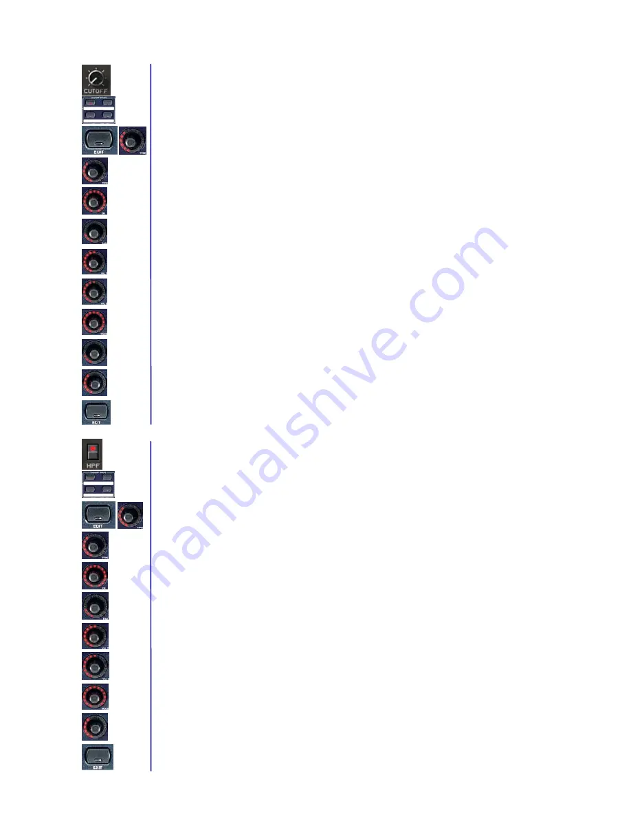
Assigning the CUTOFF parameter of the PRO-53 to the rotary function of the first push encoder on the  
B-CONTROL. PRO-53 MIDI implementation: 
CUTOFF = Control Change 70 / possible values = 0 through 127


1. Select one of the four push encoder groups by using the respective keys. 


2. Keep the EDIT key pressed and briefly turn the first push encoder, then release the EDIT key. 


3. Push Encoder 1 (TYPE): Select control change (CC). 


4. Push Encoder 2 (CH): Select a MIDI channel. This channel must correspond to the receiving channel on 

the PRO-53 (setup in the “MIDI Settings“ windows of the plug-in). 


5. Push Encoder 3 (PAR): Select controller 70. 


6. Push Encoder 4 (VAL 1 = minimal value): Select the lowest value (0). 


7. Push Encoder 5 (VAL 2 = maximum value): Select the highest value (127). 


8. Push Encoder 6 (MODE): Select “Absolute“ (AbS). 


9. Push Encoder 7 (OPTION = LED circle performance): Select “Cut“ (short for cutoff). If the encoder is 

connected, the entire LED circle lights up. When you turn the encoder to the right, the LED circle goes 
out clockwise so that only the lower right LED remains lit. 


10. Push Encoder 8 (DISPLAY VALUE = display performance): Select “ON“ to have the display show 

parameter changes when the encoder is turned. No parameters are displayed if you select “OFF.“ 


11. Exit the edit mode by pressing EXIT. 


Assigning the 

HPF

 parameter of the  

PRO-53 

to the key function of the first B-CONTROL push encoder. 

PRO-53 MIDI implementation:


HPF = Control Change 74 / possible values =  0 and 127.


1. Using the ENCODER GROUP key LEDs, you can make sure that the previously selected push encoder 

group is still active. 


2. Keep the EDIT key pressed and then briefly press the first push encoder. After that, release the EDIT 

key. 


3. Push Encoder 1 (TYPE): Select control change (CC). 


4. Push Encoder 2 (CH): Select a MIDI channel. This channel must correspond to the receiving channel on 

the PRO-53 (setup in the “MIDI Settings“ windows of the plug-in). 


5. Push Encoder 3 (PAR): Select controller 74. 


6. Push Encoder 4 (VAL 1 = ON value): Select 127 as your value. 


7. Push Encoder 5 (VAL 2 = OFF value): Select 0 as your value. 


8. Push Encoder 6 (MODE): Select “Toggle ON.“ 


9. Push Encoder 8 (DISPLAY VALUE = displays performance): Select “ON“ to have the display show 

parameter changes when the encoder is turned. No parameters are displayed if you select “OFF.“ 


10. Exit the edit mode by pressing EXIT. 

Summary of Contents for B-CONTROL

Page 1: ...ss which may be suffered by any person who relies either wholly or in part upon any description photograph or statement contained herein Colours and specification may vary slightly from product Produc...

Page 2: ...esets 5 3 Archiving presets 5 III Programming presets 6 1 Programming in manual EDIT mode 6 1 a Programming encoders BCR2000 only 6 1 b Programming push encoders 7 1 c Programming faders BCF2000 only...

Page 3: ...ommands After reading this guide you will be able to use your B CONTROL for controlling all kinds of MIDI enabled software and hardware All settings of this programming guide that do not refer to prog...

Page 4: ...tion with USB connection If you connected your computer to the B CONTROL via USB select the modes U1 through U4 2 Mode selection with double MIDI connection If you connected your B CONTROL MIDI IN and...

Page 5: ...destination preset Press the STORE key The LED and the display stop blinking and the preset is stored Details about using presets can be found in the B CONTROL user manual Note After you have programm...

Page 6: ...trol elements 1 Programming in manual EDIT mode 1 a Programming encoders BCR2000 only Assigning RESO ENV AMT and KBD parameters to the first three B CONTROL encoders PRO 53 MIDI implementation RESO CC...

Page 7: ...only the lower right LED remains lit 10 Push Encoder 8 DISPLAY VALUE display performance Select ON to have the display show parameter changes when the encoder is turned No parameters are displayed if...

Page 8: ...6 Push Encoder 5 VAL 2 maximum value Select the highest value 127 7 Push Encoder 6 MODE Select Absolute AbS 8 Exit the edit mode by pressing EXIT Repeat these steps again to assign DECAY SUSTAIN and...

Page 9: ...ogramming push encoders Assigning the CUTOFF parameter of the PRO 53 to the rotary function of the first B CONTROL push encoder 1 Select one of the four push encoder groups by using the respective key...

Page 10: ...rameter of the PRO 53 to a key on the B CONTROL 1 Keep the LEARN key pressed and briefly press the key you want to program then release the LEARN key 2 Press the INV key on your PRO 53 using the mouse...

Page 11: ...ice number This number must correspond to the receiving channel on the sequencer as a default select ALL 4 Push Encoder 3 PAR parameter Select PLAY 5 Push Encoder 6 MODE frame rate Select OFF 6 Exit t...

Reviews: