


15
BL3300 SERIES MANUAL 01/28/2013
SECTION 3
OPERATION
3.5 ANALOG REMOTE PROGRAMMING
3.5.1
REMOTE PRGM CONNECTOR
The REMOTE PRGM connector, a nine-pin connector located on the rear panel, is provided to enable the
user to program the unit remotely. A mating nine pin male connector is supplied to the user for fabricating
the cable required for remotely setting the unit's amplitude, frequency, and on dual range models, the
voltage range. It is recommended the user use AWG 20 wire to fabricate the cable. Table 1 lists the
connector pin descriptions. During remote operation, the unit's front panel VOLTS and FREQ controls
must be set fully ccw. A isolated 0 to 10 Vdc remote voltage is used to control the unit's output voltage
from 0 to full-scale and its output frequency from 45 to 500 Hz.
3.5.2
REMOTE AMPLITUDE AND FREQUENCY CONTROL
Two 0-10 Vdc control voltages from externally isolated voltage sources are used to control the unit's
amplitude and frequency via the fabricated remote cable.
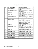
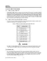
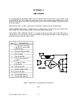
TABLE 2. REMOTE PRGM CONNECTOR PIN DESCRIPTIONS
PIN
DESCRIPTION
1
External synch HI
2
External synch LO
3
Amplitude & frequency
control (rtn).
4
Amplitude control (hi)
5
Frequency control (hi)
6
Output relay control
7
Output relay control
8
Range relay control
9
Range relay control
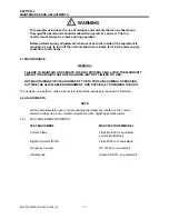
! WARNING
THE REMOTE PROGRAMMING CIRCUIT IS NOT ISOLATED FROM THE POWER SUPPLY HIGH
VOLTAGE HIGH CURRENT CIRCUITRY. EXTERNAL ISOLATION SHOULD BE PROVIDED
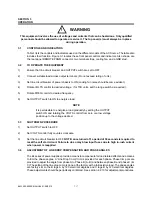
3.6 EXTERNAL SYNC
The unit provides for external synching via its rear panel REMOTE PRGM connector. When an
external sync signal is applied to the unit, it reacts to produce an output frequency that is equal to the
sync signal regardless of the FREQ control setting. The external sync can be either TTL compatible
or an AC signal from 5 to 30 VRMS.
The external sync signal applied to the unit must not be lower
than 45 Hz to avoid possible damage to the unit.
Summary of Contents for BL3300 Series
Page 9: ...3 BL3300 SERIES MANUAL 01 28 2013 ALL MANUAL ADDENDUMS WILL FOLLOW THIS PAGE ...
Page 15: ...9 BL3300 SERIES MANUAL 01 28 2013 SECTION 2 UNPACKING AND INSTALLATION ...
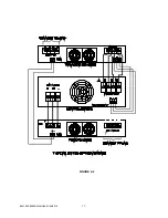
Page 17: ...11 BL3300 SERIES MANUAL 01 28 2013 FIGURE 2 2 ...
Page 20: ...14 BL3300 SERIES MANUAL 01 28 2013 ...
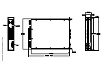
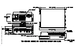
Page 33: ...3 PHASE POWER CHASSIS MECHNICAL OUTLINE ...
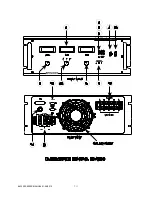
Page 34: ...BL3300 CONTROL CHASSIS MECHANICAL OUTLINE ...
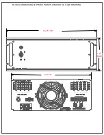
Page 35: ...BL33XX SERIES SINGLE PHASE POWER CHASSIS OUTLINE DRAWING 19 0 TYP 17 TYP 7 0 MAX ...
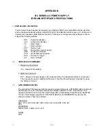
Page 54: ...6 1 SECTION 6 PARTS LIST AND DRAWINGS f ...
Page 56: ......
Page 57: ......
Page 58: ......
Page 60: ......
Page 62: ......


