background image

ASSEMBLY INSTRUCTIONS

FF-1C

B

B

A

EARTH
TUBE

B

FF-2C

FF-4C

SF-2C

EARTH

TUBE

A

Model

A

B

Min. Slab. Size

FF-1C

21-1/2”

8”

29” x 34”

FF-2C

21-3/4”

18”

28” x 44”

FF-4C

36-1/2”

18”

44” x 44”

SF-2C

27-3/4”

22”

30” x 48”

SF-4C

42-1/2"

11"

48" x 48"

CONCRETE PAD
SPECIFICATIONS

F-19859-3

Rev. 3-5-09 8-9-02

EARTH

TUBE

A

B

SF-4C

B

Summary of Contents for SF-2C

Page 1: ... the 3 4 water line to be at least 2 ft below the frost line for maximum performance Also a minimum number of animals must use the waterer to ensure that enough fresh water is cycled through the waterer daily to prevent freezing Energy Free Waterer Minimum Number of Animals Gallon Capacity SF 2C 20 40 SF 4C 30 80 EF 1C 12 15 EF 2C 20 20 EF 4C 30 30 Under certain conditions some icing may occur on ...

Page 2: ...s generally attached to the rim of the waterer body Attach the four Tie Down Brackets with the four 5 16 x 1 lag screws Use the small hole for mounting to the waterer the large hole will be used for mounting to the concrete pad DO NOT OVER TIGHTEN LAG SCREWS Just snug the bracket up to the body NOTE These Tie Down Brackets are not required on the SF 4C The SF 4C has molded in mounting pads Turn th...

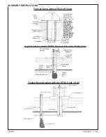
Page 3: ...Typical setup with the EFSK Shut off Kit inside Earth Tube Typical setup without Shut off Valve ASSEMBLY INSTRUCTIONS F 20560 1 Rev 6 8 09 1 10 08 Typical Remote setup with the EFSK Shut off Kit ...

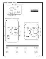
Page 4: ... 2C FF 4C SF 2C EARTH TUBE A Model A B Min Slab Size FF 1C 21 1 2 8 29 x 34 FF 2C 21 3 4 18 28 x 44 FF 4C 36 1 2 18 44 x 44 SF 2C 27 3 4 22 30 x 48 SF 4C 42 1 2 11 48 x 48 CONCRETE PAD SPECIFICATIONS F 19859 3 Rev 3 5 09 8 9 02 EARTH TUBE A B SF 4C B ...

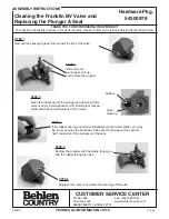
Page 5: ... tape from around the top of the valve STEP 2 Slide off cover pivot upper arm up and remove the plunger STEP 3 Clean the rubber part of the plunger and opening to the valve of any mineral deposits or dirt buildup that may be obstructing the normal operation of the valve STEP 4 If the rubber seal is grooved but still pliable not hard and brittle you may flip it over and use the backside of the seal...

Page 6: ...F 20441 4 7 06 ASSEMBLY INSTRUCTIONS ...

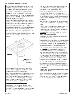
Page 7: ...of the valve When attaching the float arm to the valve be sure to attach the arm to the correct side of the valve The grooves on the valve and float arm must match Please note that the valve has coarse grooves on one side and fine grooves on the other The fine grooved side is used with the float arm see below right for details To adjust the water level in the waterer loosen the thumb screws and po...

Reviews: