background image

M U X L I C E R

P O W E R & I N T R O

P O W E R I N G T H E

M O D U L E

U S E R M A N U A L

T H A N K S F O R P U R C H A S I N G A M O D U L E F R O M B E F A C O !

B E F O R E Y O U P L U G T H I S M O D U L E I N . . .

1.

Disconnect your cabinet from the mains.

2.

Triple check the power cord polarity.

The coloured line on the cable

(pin number one) is the -12V rail.

3. If you plug the module backwards you might burn it out and

unfortunately this is not covered by the warranty.

4. If you have any questions about this product feel free to contact us:

[email protected]

I N T R O D U C T I O N

W H A T I S M U X L I C E R ?

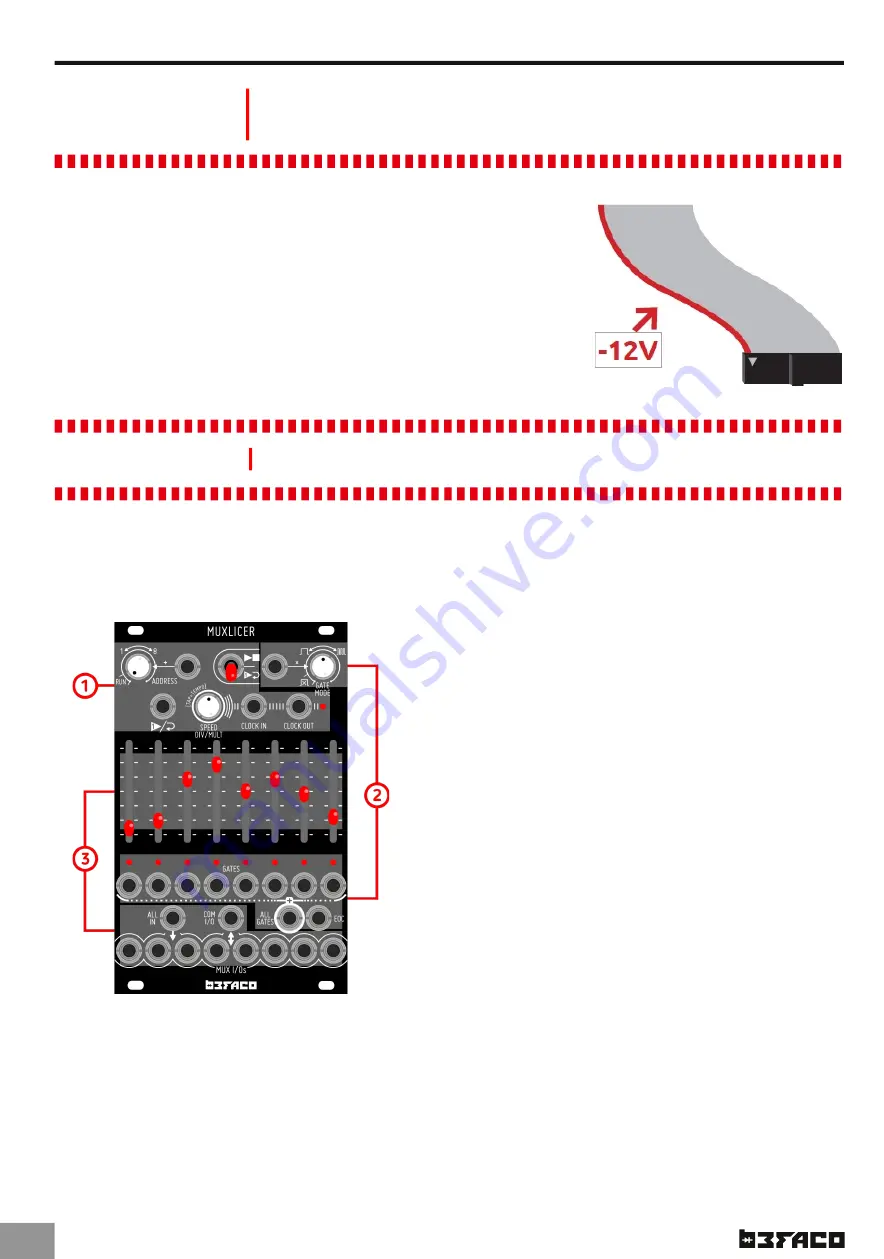
Muxlicer is an eight channel, CV addresable bidirectional analog switch and gate

generator. It is designed with a high "function per HP ratio" philosophy, to have maximum

flexibility in minimum space. It is divided in three main blocks:

1.

Digital Step Controller

Featuring Tap Tempo, Voltage controlled address

and two on board clock dividers/multipliers (one

for Clock IN and one for Clock Out).

2.

Gate Generator

With independent Mix and EOC outputs, voltage

controlled repetition and behaviour.

3.

Analog Switch (a.k.a Mux/DeMux)

Each I/O can pass analog or digital signals in

either direction.

.1

WI TH TH I S TH I N GY I N STALLED I N YOU R R ACK YOU CAN :

* Route any modular audio or CV signal from one IN up to eight OUTs or viceversa.

* Generate CV and Gate signals, been able to work as Sequencer.

* Cut audio signals in rhytmical slices with independent volume.

* Chop different audio signals in a rhytmical way.

* Generate complex CV/Gate patterns from any audio or CV moving signal.

All manuals and user guides at all-guides.com

Summary of Contents for Muxlicer

Page 1: ...M U X L I C E R U S E R M A N U A L All manuals and user guides at all guides com a l l g u i d e s c o m...

Page 2: ...All manuals and user guides at all guides com...

Page 3: ...designed with a high function per HP ratio philosophy to have maximum flexibility in minimum space It is divided in three main blocks 1 Digital Step Controller Featuring Tap Tempo Voltage controlled a...

Page 4: ...an equally voltage step relation Voltages above the maximum are just ignored 5v CV in is also possible changing the CV range switch The small switch from the back of the module 2 You can use this Inpu...

Page 5: ...r different functions 1 Tap Tempo Tap this button twice the tempo will be set at the speed of the interval between this two taps If you tap more than twice in a short time the time between them will b...

Page 6: ...CV is present the Knob acts as an attenuator 1 0v CV are accepted but most usable range is from 0 to 5v Other voltages are ignored CLOCK OU T Outputs the clock either internal or external divided or...

Page 7: ...hing is plug to this IN Muxlicer acts as normal step sequencer Explained in Speed Div Mult encoder CV Range Section M U X I Os Mux I Os are together with Common I O the main connections of Muxlicer Li...

Page 8: ...have a signal Finally you can control the level of any signal with its corresponding level fader BASI C SEQU EN CI N G Without signals presents into the Analog Switch the module works as a powerful 8...

Page 9: ...Play switch Now you can adjust the amount of retriggers in each step manually with the sliders or via CV plugin CV signals to Mux I Os If you want to reduce the maximum number of retriggers on the ste...

Reviews: