


We have divided the manual into 6 chapters, from A to F, with each chapter describing a part of
the assembly process. Within each one, we’ve numbered every step.
This way, we will have the following chapters:
A
– Assembling the structure
B
– Assembling the build plate structure
C
– Assembling the extruder
D
– Assembling the X-Axis
E
– How the 3 axes and all their components come together
F
– Assembling the Electronics
We aim to make it simple for you, so we have created areas in this manual to help you build your
helloBEEprusa as well and as easily as you can.
HOW TO READ THIS MANUAL
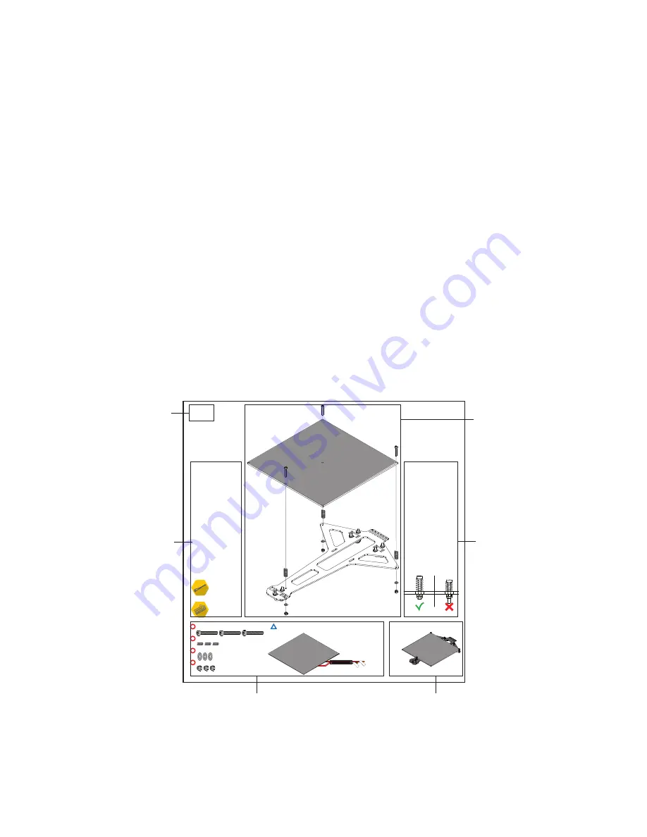
B.3
NYLOC NUT DIN985 M3
PLAIN WASHER DIN125 M3
BED SPRING
ø
0.8X2.5
CYL. HEAD SCREW DIN912 M3X20
PCB HEATED BED MK2B 214X214MM
Δ H-B
ed
Δ B
ed S
ens
or
This letter and number
will help to guide your
building process.
There is a letter for each
set of steps of the assembly,
and a number for each step.
Here you will know
what tools you might need
to use.
This area will tell you
how to build each step
Space for some tips.
What your assembly should look like
after each step.
Which kit materials you will use
for each step.
Summary of Contents for Hello BEE Prusa
Page 1: ...ASSEMBLY MANUAL ...
Page 2: ......
Page 3: ...V3 310815 ...
Page 10: ...A ASSEMBLING THE STRUCTURE ...
Page 11: ...A 1 STRUCTURE ...
Page 14: ...BUTTON HEAD SCREW DIN7380 M4X10 SERRATED LOCK WASHER DIN6798J M4 HEX THIN NUT 1 DIN439 M4 A 4 ...
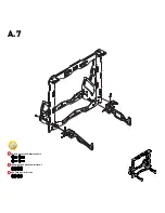
Page 17: ...BUTTON HEAD SCREW DIN7380 M4X10 SERRATED LOCK WASHER DIN6798J M4 HEX THIN NUT 1 DIN439 M4 A 7 ...
Page 22: ...B ASSEMBLING THE BUILD PLATE STRUCTURE ...
Page 26: ...B 4 END STOP LEVER X Y ...
Page 28: ...B 6 BUTTON HEAD SCREW DIN7380 M4X10 SERRATED LOCK WASHER DIN6798J M4 HEX THIN NUT 1 DIN439 M4 ...
Page 29: ...C ASSEMBLING THE EXTRUDER ...
Page 30: ...C 1 STRUCTURE ...
Page 38: ...C 9 END STOP LEVER X Y ...
Page 39: ...D ASSEMBLING THE X AXIS ...
Page 40: ...D 1 X SUPPORT HEX THIN NUT 2 D439 M5 LINEAR GUIDE 8X385MM X STRUCTURE ...
Page 43: ...D 4 X SUPPORT C EXTRUDER HEX THIN NUT 2 DIN439 M5 ...
Page 44: ...D 5 STRUCTURE ...
Page 47: ...D 8 CYL HEAD SCREW D912 M3X30 ADJUSTABLE Z END STOP ...
Page 48: ...E HOW THE 3 AXES AND ALL THEIR COMPONENTS COME TOGETHER ...
Page 50: ...E 2 LINEAR GUIDE 8X335MM Z Guides should slide freely ...
Page 51: ...E 3 After this step move the extruder to feel if it slides freely on both axies X and Z ...
Page 53: ...E 5 THREADED ROD DIN976 A2 M5X320 ...
Page 55: ...E 7 GT2 RUBBER BELT CABLE TIE 2 5X100MM Place to put the Cable Tie ...
Page 56: ...F ASSEMBLING THE ELECTRONICS ...