


To make recognizing each type of component easier, we’ve assigned a shape and colour to each type.
Structure parts
Mechanics
Printed parts
Electronics
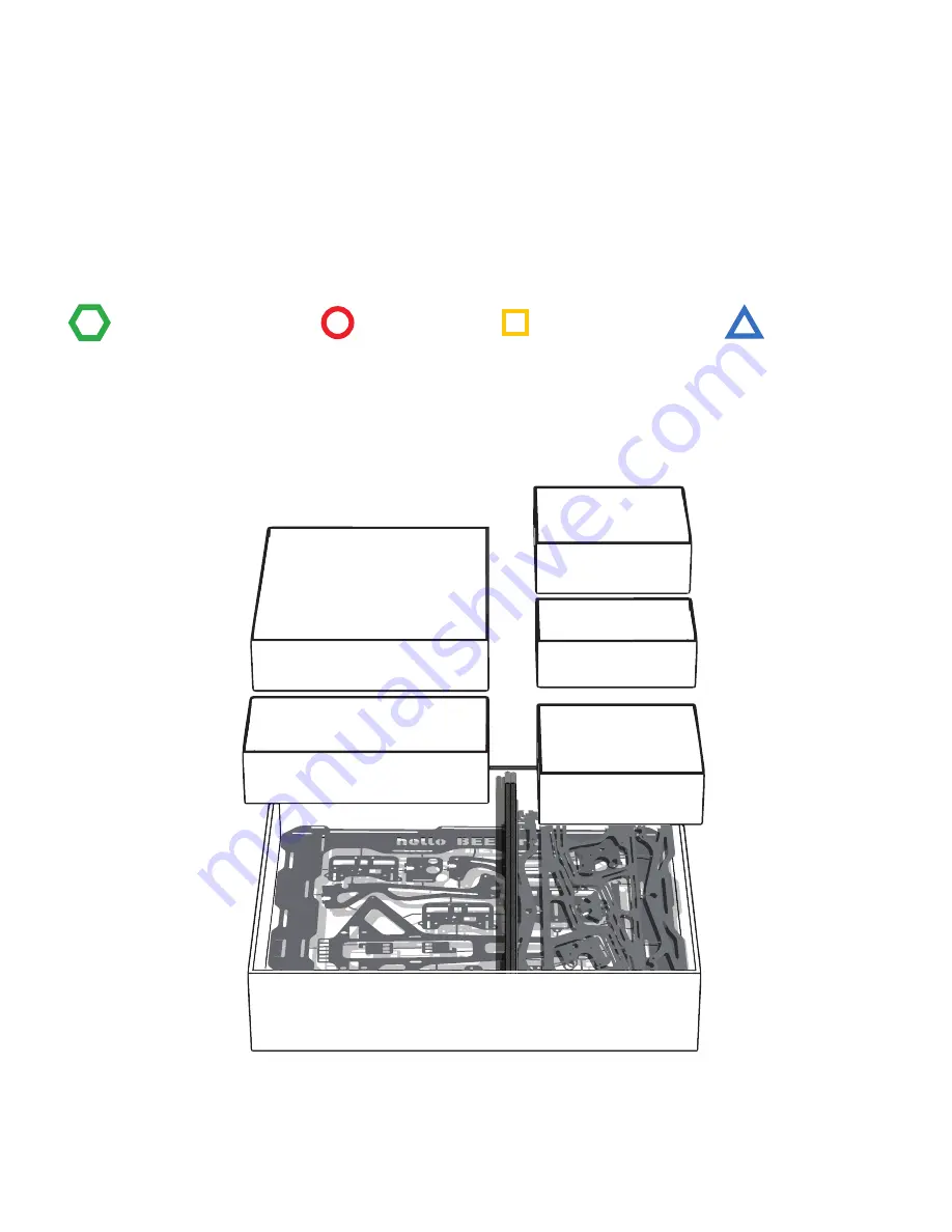
WHAT COMES WITH THE PACKAGE
BOX 1
Inside this box you have
almost all the Electronic
components, as well as the glass
and heated bed, and you
have the Printed Parts too.
BOX 3
All the motors needed
are inside this box.
BOX 4
Behold the Motherboard
MKS Gen V1.2 with 5 drv8825
and stepper driver.
BOX 5
All the Mechanic Parts
you need are right here.
BOX 2
In this box you have
the Power Supply
BOX 0
Main Metal Frame
of your helloBEEprusa,
guides and Threaded Rods.
BOX 1
BOX 2
BOX 5
BOX 4
BOX 3
This way, we tried to divide all the components in boxes, just to make it easy for you.
BOX 0
Summary of Contents for Hello BEE Prusa
Page 1: ...ASSEMBLY MANUAL ...
Page 2: ......
Page 3: ...V3 310815 ...
Page 10: ...A ASSEMBLING THE STRUCTURE ...
Page 11: ...A 1 STRUCTURE ...
Page 14: ...BUTTON HEAD SCREW DIN7380 M4X10 SERRATED LOCK WASHER DIN6798J M4 HEX THIN NUT 1 DIN439 M4 A 4 ...
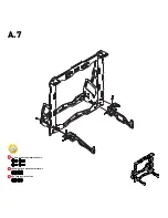
Page 17: ...BUTTON HEAD SCREW DIN7380 M4X10 SERRATED LOCK WASHER DIN6798J M4 HEX THIN NUT 1 DIN439 M4 A 7 ...
Page 22: ...B ASSEMBLING THE BUILD PLATE STRUCTURE ...
Page 26: ...B 4 END STOP LEVER X Y ...
Page 28: ...B 6 BUTTON HEAD SCREW DIN7380 M4X10 SERRATED LOCK WASHER DIN6798J M4 HEX THIN NUT 1 DIN439 M4 ...
Page 29: ...C ASSEMBLING THE EXTRUDER ...
Page 30: ...C 1 STRUCTURE ...
Page 38: ...C 9 END STOP LEVER X Y ...
Page 39: ...D ASSEMBLING THE X AXIS ...
Page 40: ...D 1 X SUPPORT HEX THIN NUT 2 D439 M5 LINEAR GUIDE 8X385MM X STRUCTURE ...
Page 43: ...D 4 X SUPPORT C EXTRUDER HEX THIN NUT 2 DIN439 M5 ...
Page 44: ...D 5 STRUCTURE ...
Page 47: ...D 8 CYL HEAD SCREW D912 M3X30 ADJUSTABLE Z END STOP ...
Page 48: ...E HOW THE 3 AXES AND ALL THEIR COMPONENTS COME TOGETHER ...
Page 50: ...E 2 LINEAR GUIDE 8X335MM Z Guides should slide freely ...
Page 51: ...E 3 After this step move the extruder to feel if it slides freely on both axies X and Z ...
Page 53: ...E 5 THREADED ROD DIN976 A2 M5X320 ...
Page 55: ...E 7 GT2 RUBBER BELT CABLE TIE 2 5X100MM Place to put the Cable Tie ...
Page 56: ...F ASSEMBLING THE ELECTRONICS ...


