background image

Foreword

KL3222

5

Version: 2.3.0

1

Foreword

1.1

Notes on the documentation

Intended audience

This description is only intended for the use of trained specialists in control and automation engineering who
are familiar with the applicable national standards.
It is essential that the documentation and the following notes and explanations are followed when installing
and commissioning these components.
It is the duty of the technical personnel to use the documentation published at the respective time of each
installation and commissioning.

The responsible staff must ensure that the application or use of the products described satisfy all the
requirements for safety, including all the relevant laws, regulations, guidelines and standards.

Disclaimer

The documentation has been prepared with care. The products described are, however, constantly under
development.

We reserve the right to revise and change the documentation at any time and without prior announcement.

No claims for the modification of products that have already been supplied may be made on the basis of the
data, diagrams and descriptions in this documentation.

Trademarks

Beckhoff

®

, TwinCAT

®

, EtherCAT

®

, EtherCAT G

®

, EtherCAT G10

®

, EtherCAT P

®

, Safety over EtherCAT

®

,

TwinSAFE

®

, XFC

®

, XTS

®

 and XPlanar

®

 are registered trademarks of and licensed by Beckhoff Automation

GmbH. Other designations used in this publication may be trademarks whose use by third parties for their
own purposes could violate the rights of the owners.

Patent Pending

The EtherCAT Technology is covered, including but not limited to the following patent applications and
patents: EP1590927, EP1789857, EP1456722, EP2137893, DE102015105702 with corresponding
applications or registrations in various other countries.

EtherCAT

®

 is registered trademark and patented technology, licensed by Beckhoff Automation GmbH,

Germany.

Copyright

© Beckhoff Automation GmbH & Co. KG, Germany.
The reproduction, distribution and utilization of this document as well as the communication of its contents to
others without express authorization are prohibited.
Offenders will be held liable for the payment of damages. All rights reserved in the event of the grant of a
patent, utility model or design.

Summary of Contents for KL3222

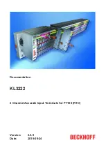
Page 1: ...Documentation KL3222 2 Channel Accurate Input Terminals for PT100 RTD 2 3 0 2019 09 24 Version Date...

Page 2: ......

Page 3: ...ielding 20 3 4 4 Pin assignment 21 3 5 ATEX Special conditions standard temperature range 22 3 6 ATEX Documentation 23 4 Configuration Software KS2000 24 4 1 KS2000 Introduction 24 4 2 Parameterizatio...

Page 4: ...Table of contents KL3222 4 Version 2 3 0...

Page 5: ...tion of products that have already been supplied may be made on the basis of the data diagrams and descriptions in this documentation Trademarks Beckhoff TwinCAT EtherCAT EtherCAT G EtherCAT G10 Ether...

Page 6: ...ained specialists in control automation and drive engineering who are familiar with the applicable national standards Description of instructions In this documentation the following instructions are u...

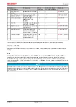
Page 7: ...program added to chapter KS2000 Configuration software Update structure 2 0 0 Migration 1 1 0 Register description expanded Parameterization with KS2000 extended 1 0 0 First public issue Firmware and...

Page 8: ...product it can be found in the following places on the packaging unit directly on the product if space suffices on the packaging unit and the product The BIC is machine readable and contains informat...

Page 9: ...s are used by Beckhoff and serve internal processes Structure of the BIC Example of composite information from item 1 to 4 and 6 The data identifiers are marked in red for better display BTN An import...

Page 10: ...st be used for 2 3 wire connection technology Linearization over the full temperature range is realized with the aid of a microprocessor The temperature range can be selected freely The Bus Terminal s...

Page 11: ...nting rail conforms to EN 60715 Permissible ambient temperature range during operation 0 C 55 C Permissible ambient temperature range during storage 25 C 85 C Permissible relative air humidity 95 no c...

Page 12: ...with highly insulating materials synthetic fibers plastic film etc Surroundings working place packaging and personnel should by grounded probably when handling with the devices Each assembly must be t...

Page 13: ...lock clicks onto the mounting rail If the terminals are clipped onto the mounting rail first and then pushed together without tongue and groove the connection will not be operational When correctly a...

Page 14: ...ents The six spring contacts of the K Bus E Bus deal with the transfer of the data and the supply of the Bus Terminal electronics The power contacts deal with the supply for the field electronics and...

Page 15: ...sting or to damage on the terminal e g disruptive discharge to the PE line during insulation testing of a consumer with a nominal voltage of 230 V For insulation testing disconnect the PE supply line...

Page 16: ...load capacity the following additional installation instructions apply The enhanced mechanical load capacity is valid for all permissible installation positions Use a mounting rail according to EN 60...

Page 17: ...nsity Standard wiring ELxxxx KLxxxx Fig 7 Standard wiring The terminals of ELxxxx and KLxxxx series have been tried and tested for years They feature integrated screwless spring force technology for f...

Page 18: ...sign as the packaging density is twice as large as that of the standard 12 mm Bus Terminals Massive conductors and conductors with a wire end sleeve can be inserted directly into the spring loaded ter...

Page 19: ...e wire size width Terminal housing ELxxxx KLxxxx ESxxxx KSxxxx Wire size width single core wires 0 08 2 5 mm2 0 08 2 5 mm2 Wire size width fine wire conductors 0 08 2 5 mm2 0 08 2 5 mm2 Wire size widt...

Page 20: ...Mounting and wiring KL3222 20 Version 2 3 0 3 4 3 Shielding Shielding Encoder analog sensors and actors should always be connected with shielded twisted paired wires...

Page 21: ...Bring the Bus Terminals system into a safe de energized state before starting mounting disassembly or wiring of the Bus Terminals Fig 11 Pin assignment KL3222 Terminal point No Connection for R1 1 Cha...

Page 22: ...ed operating voltage being exceeded by more than 40 due to short term interference voltages The individual terminals may only be unplugged or removed from the Bus Terminal system if the supply voltage...

Page 23: ...e Beckhoff terminal systems in potentially explosive ar eas ATEX Pay also attention to the continuative documentation Notes about operation of the Beckhoff terminal systems in potentially explosive ar...

Page 24: ...s Box Modules can be prepared before the commissioning phase Later on this configuration can be transferred to the terminal station in the commissioning phase by means of a download For documentation...

Page 25: ...es directly online The same high level dialogs and register access are available for this purpose as in the configuration phase The KS2000 offers access to the process images of the bus couplers and F...

Page 26: ...for the connected fieldbus station In the example shown this is an Ethernet Coupler BK9000 a digital input terminal KL1xx2 a KL3222 a KL9010 bus end terminal Fig 13 Display of the fieldbus station in...

Page 27: ...the KL3222 registers The dialog mask for the parameterization of the KL3222 can be found under Settings 27 ProcData displays the KL3222 process data 4 3 Settings The dialog mask for parameterization...

Page 28: ...terminal R37 38 50 Hz default value 60 Hz 100 Hz 500 Hz 1000 Hz 2000 Hz 3750 Hz 7500 Hz 15000 Hz 30000 Hz 5 Hz 10 Hz Resistance thermometer sensor type Here you can adjust the KL3222 to the connected...

Page 29: ...ent explicitly do not refer to specific applications The customer is therefore responsible for assessing and deciding whether the product is suitable for a particular application We accept no responsi...

Page 30: ...coupler e g BK1120 or embedded PC KL3314 KL9010 Download https infosys beckhoff com content 1033 kl3222 Resources zip 5996114571 zip Preparations for starting the sample programs tnzip file TwinCAT 3...

Page 31: ...figuration of the example Checking NetId the EtherCAT tab of the EtherCAT device shows the configured NetId The first 4 numbers have to be identical with the project NetId of the target system The pro...

Page 32: ...SB1 33 CB1 33 1 2 Word DataIN1 3 4 Byte SB2 33 CB2 33 4 6 Word DataIN2 Compact process image The KL3222 is represented in the compact process image with 4 bytes input data and without output data Thes...

Page 33: ...on is enabled A gain and offset calibration of the terminal can be carried out with the control byte in process data mode The code word must be entered in register R31 so that the calibration can be c...

Page 34: ...ead access 1bin Write access CB1 5 to CB1 0 Reg no Register number Enter the number of the register 35 that you want to read with input data word DataIn 32 or want to write with output data word DataO...

Page 35: ...OM R11 Signal channels 0x0218 536dec R ROM R12 minimum data length of a channel 0x0098 152dec R ROM R13 Data structure 0x0004 4dec R ROM R14 reserved R15 Alignment register variable variable R W RAM R...

Page 36: ...status byte are not mandatory for the terminal function and are not transferred in compact mode R16 hardware version number Register R16 contains the hardware version of the terminal R17 manufacturer...

Page 37: ...TY83122 30dec KTY83151 31dec KTY83152 32dec KTY84130 33dec KTY84151 34dec KTSIEMENS1K 35dec KTSIEMENS2K_5 36dec KTSIEMENS2K_7 37dec KTSIEMENS1K_5 38dec KTSIEMENS1K_7 others reserved R32 7 R 32 6 Conne...

Page 38: ...ding the firmware version from Register 9 Output Data Byte 0 Control byte Byte 1 DataOUT1 high byte Byte 2 DataOUT1 low byte 0x89 1000 1001bin 0xXX 0xXX Explanation Bit 0 7 set means Register communic...

Page 39: ...de word 0x1235 for deactivating write protection Input Data answer of the bus terminal Byte 0 Status byte Byte 1 DataIN1 high byte Byte 2 DataIN1 low byte 0x9F 1001 1111bin 0xXX 0xXX Explanation The t...

Page 40: ...fore changing the values Input data response from the Bus Terminal Byte 0 Status byte Byte 1 DataIN1 high byte Byte 2 DataIN1 low byte 0xA0 1010 0000bin 0xXX 0xXX Explanation The terminal returns a va...

Page 41: ...ecify the register number 31 with 01 1111bin The output data word byte 1 and byte 2 contains 0x0000 for reactivating write protection Input Data answer of the bus terminal Byte 0 Status byte Byte 1 Da...

Page 42: ...ckhoff components there Beckhoff Headquarters Beckhoff Automation GmbH Co KG Huelshorstweg 20 33415 Verl Germany Phone 49 5246 963 0 Fax 49 5246 963 198 e mail info beckhoff com Beckhoff Support Suppo...

Page 43: ...wiring 17 Fig 8 Pluggable wiring 17 Fig 9 High Density Terminals 18 Fig 10 Connecting a cable on a terminal point 19 Fig 11 Pin assignment KL3222 21 Fig 12 KS2000 configuration software 24 Fig 13 Dis...

Reviews: