Access from the user program
KL3208, KL3228/KS3228
42
Version: 3.3.0
5.4
Register description
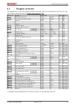
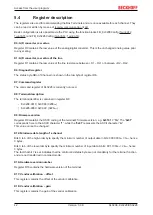
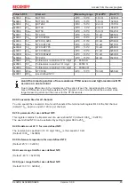
The registers are used for parameterizing the Bus Terminals and are once available for each channel. They
can be read or written by means of
.
Basic configuration is also possible via the PLC using the function blocks FB_KL3208Config (
,
R0: A/D converter, raw value
Register R0 contains the raw value of the analog/digital converter. This is the unchanged analog value prior
to any scaling.
R1: A/D converter, raw value of the line
Register R1 contains the raw value of the line resistance bR1 – RL1 or bR2 – RL2.
R6: Diagnostic register
The status byte SBn of Channel n is shown in the low byte of register R6.
R7: Command register
The command register of KL3228 is currently not used.
R8: Terminal description
The terminal identifier is contained in register R8:
• KL3208-0010: 0x0C88 (3208
dec
)
• KL3228-0000: 0x0C9C (3228
dec
)
R9: Firmware version
Register R9 contains the ASCII coding of the terminal's firmware version, e.g.
0x3141
= '1A'
. The
'0x31'
corresponds here to the ASCII character
'1'
, while the
'0x41'
represents the ASCII character
'A'
.
This value cannot be changed.
R12: Minimum data length of a channel
Bits 0 to 6 of the high-order byte specify the minimum number of output data in bits: 000.0000
bin
= 0
dec
, hence
0 bytes.
Bits 0 to 6 of the low-order byte specify the minimum number of input data in bits: 001.1000
bin
= 24
dec
, hence
3 bytes.
The fact that bit 7 is set indicates that the control and status byte are not mandatory for the terminal function
and are not transferred in compact mode.
R16: Hardware version number
Register R16 contains the hardware version of the terminal.
R17: Vendor calibration – offset
This register contains the offset of the vendor calibration.
R18: Vendor calibration – gain
This register contains the gain of the vendor calibration.


