background image

General Notes 


General Notes 


Notes on the documentation 


This description is only intended for the use of trained specialists in control 
and automation engineering who are familiar with the applicable national 
standards. It is essential that the following notes and explanations are 
followed when installing and commissioning these components. 


Liability conditions 


The responsible staff must ensure that the application or use of the 
products described satisfy all the requirements for safety, including all the 
relevant laws, regulations, guidelines and standards. 

The documentation has been prepared with care. The products described 
are, however, constantly under development. For this reason, the 
documentation may not always be have been fully checked for consistency 
with the performance data, standards or other characteristics described. 
None of the statements in this manual represent a guarantee for as set out 
in § 443 of the German Civil Code or a statement about the assumed use 
according to the contract as set out in § 434 para. 1 clause 1 no. 1 of the 
German Civil Code. In the event that it contains technical or editorial errors, 
we retain the right to make alterations at any time and without warning. No 
claims for the modification of products that have already been supplied 
may be made on the basis of the data, diagrams and descriptions in this 
documentation.


© This documentation is protected by copyright. Any reproduction or third 
party use of this publication, whether in whole or in part, without the written 
permission of Beckhoff Automation GmbH, is forbidden. 


Description of safety symbols 


The following safety symbols are used in this operating manual. They are 
intended to alert the reader to the associated safety instructions. 


Danger


This symbol is intended to highlight risks for the life or health of personnel. 


Warning


This symbol is intended to highlight risks for equipment, materials or the 
environment. 


i


Note


This symbol indicates information that contributes to better understanding. 


2


 CP77xx 

Summary of Contents for CP7700

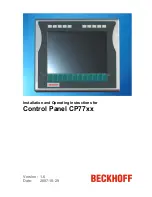
Page 1: ...Installation and Operating instructions for Control Panel CP77xx Version 1 6 Date 2007 10 29...

Page 2: ......

Page 3: ...sport 7 Unpacking 7 Assembly 8 Assembly dimensions 8 Connecting the Control Panel 9 Connecting cables 9 Protective Earthing 9 Operating Instructions 10 Functional description 10 Keyboard codes 10 Comp...

Page 4: ...et out in 443 of the German Civil Code or a statement about the assumed use according to the contract as set out in 434 para 1 clause 1 no 1 of the German Civil Code In the event that it contains tech...

Page 5: ...rol Panel side Items of equipment that have been switched off must be secured against being switched on again Danger Displays used for the control panel s LC display are operated with a voltage of up...

Page 6: ...regulations cover amongst other things the intervals between inspections of the controller The operator must initiate such inspections in good time Procedure in the event of a fault In the event of fa...

Page 7: ...ontrol Panel in areas of explosive hazard The Control Panel must not be used where there is a risk of explosion Connections Control Panel CP77XX connections Pin assignment X 100 Serial interface SG 12...

Page 8: ...to AG Co KG the protection class accords to the IP67 standard Protective Earthing Protective Earthing The low resistance protective earthing connection is established via the ground bolt which is loca...

Page 9: ...n temperature make sure that moisture condensation does not form on or inside the device Prior to operation the unit must be allowed to slowly adjust to room temperature Should condensation occur a de...

Page 10: ...711 12 Display 353 8 326 3 27 5 327 6 303 7 CP7712 15 Display 426 395 28 5 399 8 367 4 Control Panel CP772x Dimensions a b t A B CP7729 6 5 Display 336 213 38 310 189 CP7720 10 Display 406 308 3 27 5...

Page 11: ...plug Do not pull the cable Connecting cables The connections are located at the rear of the Control Panel and are documented in the Product Description section When connecting cables to the Control P...

Page 12: ...be operated with a touch screen pen The touch screen may only be actuated by finger tips or with the touch screen pen The operator may wear gloves but there must be no hard particles such as metal sha...

Page 13: ...ng of another key that is pressed at the same time This key brings up the Start menu of the operating system in use Windows 95 98 ME NT 2000 XP Pressing this key opens the property sheet of the active...

Page 14: ...over To change the CF card first of all unscrew the four screws see above photo with a crosstip screwdriver The aluminium cover can be removed and enables access to the memory card see below photo Rem...

Page 15: ...fluorescent lamps represent a consumable item in a display they must be replaced after a few years depending on the number of operating hours The fluorescent lamps of the 6 5 inch 12 inch and 15 inch...

Page 16: ...5 inch TFT display NL6448BC20 08 C9900 L364 12 inch TFT display LTD121C30S C9900 L366 15 inch TFT display LQ150X1LW71N Emergency procedures In case of fire the control panel should be extinguished wi...

Page 17: ...Beckhoff Service Control Panel boots software starts but control does not operate correctly The cause of the error is in the software or in parts of the equipment outside the control panel Call the m...

Page 18: ...e 5 D 33415 Verl Germany Phone 49 0 5246 963 0 Fax 49 0 5246 963 198 e mail info beckhoff com Beckhoff Support Support offers you comprehensive technical assistance helping you no only with the appli...

Page 19: ...n Suitable packaging of the Control Panel can improve the resistance to impact during transport The ambient temperature during storage and transport must be between 20 C and 65 C i Note Pixel errors i...

Reviews: