background image

Foreword 


1.4  Operator’s obligation to exercise diligence 

The operator must ensure that 

• 

the product is only used as intended (see chapter


Product Description

• 

the product is in a sound condition and in working order during operation 

• 

the product is operated, maintained and repaired only by suitably qualified and authorized 
personnel 

• 

the personnel is instructed regularly about relevant occupational safety and environmental 
protection aspects, and is familiar with the operating manual and in particular the safety notes 
contained herein 

• 

the operation manual is in good condition and complete, and always available for reference at the 
location of the product. 


Do not open the housing of the Control Panel! 


Note 

For technical support contact

 Beckhoff Service


1.4.1 National regulations 

Depending on the type of machine and plant in which the Control Panel is used, national regulations 
governing the controllers of such machines will apply, and must be observed by the operator. These 
regulations cover, amongst other things, the intervals between inspections of the controller. The operator 
must initiate such inspections in good time. 

1.4.2  Procedure in the event of a fault 

In the event of faults at the Control Panel, the list in the section 

Troubleshooting 

can be used to determine 

the measures to be taken. 

1.4.3 Operator requirements 

Anyone who uses the Control Panel must have read these operating instructions and must be familiar 
with all the functions of the software installed on the Industrial PC to which he has access. 


6


CP29xx 

Summary of Contents for CP29xx-0000 Series

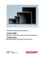
Page 1: ...stallation and Operating instructions for CP29xx 0000 Multi touch Control Panel with DVI USB Extended interface CP29xx 0010 Multi touch Control Panel with CP Link 4 interface Version 1 9 Date 2018 11...

Page 2: ......

Page 3: ...Access to the connectors 8 2 4 Interfaces CP29xx 0000 10 2 4 1 DVI E Input Digital Visual Interface Extended X106 10 2 4 2 USB Extended Input X 105 10 2 4 3 USB in X 104 11 2 4 4 USB out X 102 X 103 1...

Page 4: ...22 5 Operating Instructions 23 5 1 Switching the Control Panel on and off 23 5 1 1 Switching on 23 5 1 2 Shutting down and switching off 23 5 2 Operation 23 5 3 Servicing and maintenance 24 5 3 1 Cle...

Page 5: ...C and XTS are registered trademarks of and licensed by Beckhoff Automation GmbH Other designations used in this publication may be trademarks whose use by third parties for their own purposes could vi...

Page 6: ...duals Risk of injury WARNING If you do not adhere the safety advise adjoining this symbol there is danger to life and health of individuals Hazard to individuals CAUTION If you do not adhere the safet...

Page 7: ...ir all parts of the equipment must first be switched off after which the Control Panel is to be disconnected from the equipment Disconnect the device by unplugging the connectors on the rear side of t...

Page 8: ...pen the housing of the Control Panel Note For technical support contact Beckhoff Service 1 4 1 National regulations Depending on the type of machine and plant in which the Control Panel is used nation...

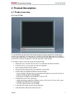
Page 9: ...3 landscape and portrait orientation multi touch PCT e g for 5 finger or 2 hand touch operation high touch point density for safe operation aluminium housing with glass front front side IP65 rear side...

Page 10: ...nce of up to 50 m from the PC via a standard cable The CP Link 4 connection technology integrated in the CP29xx 0010 Control Panel enables remote panel operation at a distance of up to 100 m from the...

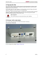
Page 11: ...Product Description Connection block CP29xx 0010 For the pin assignment see chapter Interfaces CP29xx 0010 CP29xx 9...

Page 12: ...he CP29xx Control Panel features a signal processor that restores the DVI signal The PC requires a conventional DVI output Pin Signal Pin Signal 1 Rx2 13 Rx3 2 Rx2 14 5V DVI 3 GND 15 GND 4 Rx4 16 HPD...

Page 13: ...supported in a distance of up to 3 m from the PC from a distance of 3 m up to 50 m or if using USB Extended USB2 0 standard is supported Pin Signal Pin Signal 1 5V 3 D 2 D 4 GND 2 4 5 Ground connecti...

Page 14: ...up to 100 m away from the PC CP Link 4 transfers DVI and USB together via a CAT 6A cable The CU8802 CP Link 4 transmitter box is connected to the PC via DVI and USB or else the C9900 E276 PCIe module...

Page 15: ...ins unchanged The CU8803 sender box provides power to the Control Panel via the CAT 6A cable which also transfers DVI and USB The power supply socket of the panel is not used Don t connect power suppl...

Page 16: ...nk 4 Input X104 X104 BA 1x8pole RJ45 Invers shield 2XLWL Lp mount Molex Nr 43860 0016 Modular Jack The Control Panel is connected with the PCIe module slot of the Industrial PC or the transmitter box...

Page 17: ...e Control Panel is established via the socket X101 see chapter CP Link 4 Architecture Description The power supply connector is included in delivery Pin Signal Pin Signal 1 NC 4 GND 2 NC 5 24 VDC Powe...

Page 18: ...C9900 K627 Connecting kit 30 m for CP29xx containing 30 m DVI cable 30 m CAT 5 cable for USB E 2 0 USB to USB E 2 0 converter CU8801 for mounting rail installation close to the PC and 1 m USB cable t...

Page 19: ...nnecting cable RJ45 CAT 6A 90 m C9900 K682 Connecting cable RJ45 CAT 6A 100 m C9900 K725 Connecting cable RJ45 CAT 6A 3 m suitable as trailing cable C9900 K713 Connecting cable RJ45 CAT 6A 5 m suitabl...

Page 20: ...oisture condensation does not form on or inside the device Prior to operation the unit must be allowed to slowly adjust to room temperature Should condensation occur a delay time of approximately 12 h...

Page 21: ...to direct sunlight When the unit is in its mounting position the ventilation openings must not be obstructed Avoid extreme environmental conditions Attention Extreme environmental conditions should b...

Page 22: ...levers For the cutout dimension of the Control Panel see chapter Assembly dimensions the wall thickness is between 1 mm and 5 mm 1 Insert the Control Panel into the cutout 2 Release the clamping leve...

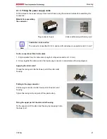
Page 23: ...is fitted to the cable 1 Strip insulation from the cable ends Length of stripped conductor is 8 9 mm 2 Screw together the cable ends in the 5 pole plug connector in accordance with wiring diagram Appl...

Page 24: ...onnections are located at the rear of the Control Panel and are documented in the chapter Interfaces When connecting cables to the Control Panel please adhere to the following order Disconnect the Con...

Page 25: ...ing off while the software is running is very high Switch off power supply Warning When you have shut down the Industrial PC you have to switch off power supply for at least 10 seconds before rebootin...

Page 26: ...ree 5 4 Emergency procedures In case of fire the Control Panel should be extinguished with powder or nitrogen 5 5 Shutting down 5 5 1 Disposal Observe national electronics scrap regulations Note Obser...

Page 27: ...operate correctly Cause of the fault is either in the software or in parts of the plant outside the Industrial PC Call the manufacturer of the machine or the software Malfunction of the touchscreen B...

Page 28: ...lease visit our homepage Here you will find the actual drawings using the link http download beckhoff com download Technical_Drawings Industrial_PC Control_Panel CP29xx Notice mounting orientation War...

Page 29: ...with 480 Mbit s DVI E input is compatible to the standard DVI output of a PC CP29xx 0010 Integrated CP Link 4 technology enables remote panel operation at a distance of up to 100 m from the PC via a C...

Page 30: ...Co KG Huelshorstweg 20 33415 Verl Germany Phone 49 0 5246 963 0 Fax 49 0 5246 963 198 E mail info beckhoff de Web http www beckhoff de Beckhoff Support Support offers you comprehensive technical assis...

Page 31: ...nerates uses and can radiate radio frequency energy and if not installed and used in accordance with the instruction manual may cause harmful interference to radio communications Operation of this equ...

Reviews: