Beckhoff AX8911 Documentation Download Page 44

Safe Motion functions

AX8911

44

Version: 1.2.0

7.4

Basic functions

7.4.1

Signal assignment

The process data of the AX8911 supply information about the current state of the safety card and the
SafeMotion functions.

The following notes and signal assignments must be taken into account by the user and implemented
according to the user configuration.

Switch-off paths and restart lock

 WARNING

STO function

For the STO function, all 4 STO signals of an axis must be switched by the safety application.

 WARNING

Restart lock

After activating the STO function, the restart lock must be implemented in the safety application. If the result
of the risk and hazard analysis is that the restart must be implemented via a safe signal, then the restart
must be wired to a safe TwinSAFE signal.

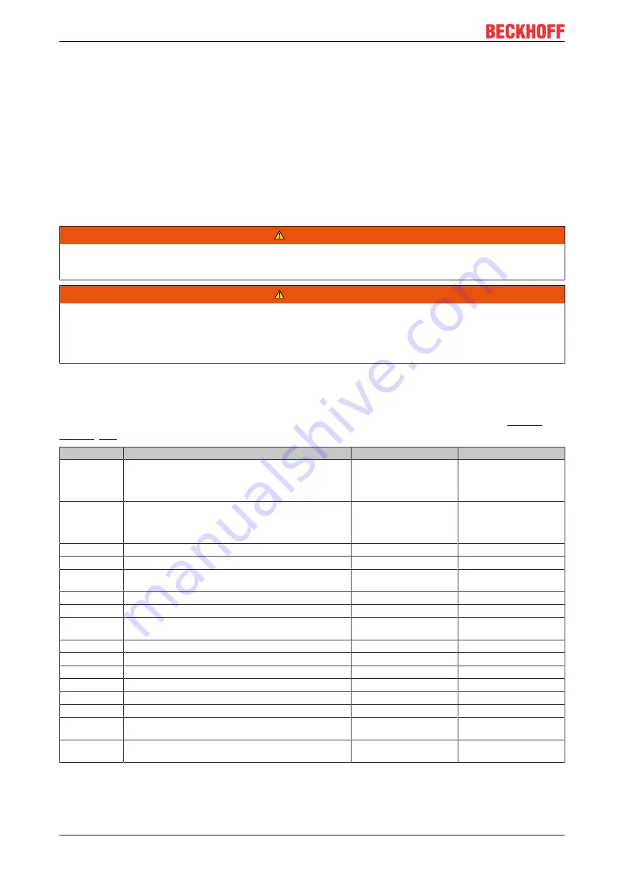
Assignment of the AX8000 signals (minimum configuration)

The table below contains a list of the signals that must at least be exchanged between the AX8911 and the
AX8000. The addresses and descriptions for source and destination can be found in the chapter 

Process

image [

}

 38]

.

Name

Description Axis 1

Source (SafeIn)

Destination (SafeOut)

Group-
Port_RunStop

This signal is automatically created when creating the Twin-
SAFE group and can be placed on a standard signal. If the
signals from the AX8000 are to be used, the adjacent as-
signment can be used.

22.0

GroupPort_RunStop

GroupPort_Er-
rAck

This signal is automatically created when creating the Twin-
SAFE group and can be placed on a standard signal. If the
signals from the AX8000 are to be used, the adjacent as-
signment can be used.

22.1

GroupPort_ErrAck

ErrAck_STO1

Acknowledgement of an STO module fault

22.1

0.4

ErrAck_Brake1 Acknowledgement of a brake module fault

22.1

1.5

Er-
rAck_SAFEIN1

Acknowledgement of a SafeIN module fault

22.1

2.2

ErrAck_Enc1

Acknowledgement of an encoder module fault

22.1

4.0

ErrAck_Prim1

Acknowledgement of a module fault in the primary feedback 22.1

14.0

Errack_Sec1

Acknowledgement of a module fault in the secondary feed-
back

22.1

18.0

STOerror1

Module error in the STO module for Axis 1

0.0

6.1

FSINerror1

Module error in the FSIN module for Axis 1

1.0

6.2

BrakeError1

Module error in the brake module for Axis 1

0.2

6.3

UnderRange1

Encoder Underrange Error

2.0

6.4

OverRange1

Encoder Overrange Error

2.1

6.5

EncEnable1

Encoder Enable

2.3

6.6

PrimError1

Error occurred in the primary feedback
Default OCT / Endat 2.2 (depending on active feedback)

56.0 / 56.1

6.7

SecError1

Error occurred in the secondary feedback
Default OCT / Endat 2.2 (depending on active feedback)

82.0 / 82.1

7.0

Summary of Contents for AX8911

Page 1: ...Documentation for AX8911 TwinSAFE Drive Option for AX8xxx xxxx Servo Drives 1 2 0 2020 03 30 Version Date...

Page 2: ......

Page 3: ...5 1 Environmental conditions 19 5 2 Installation 19 5 2 1 Safety instructions 19 5 2 2 Transport storage 19 5 2 3 Mechanical installation 19 5 2 4 Electrical installation 20 5 3 Configuration of the o...

Page 4: ...S 51 7 9 Safety function SAR SMA 51 7 10 Safety function SDI 52 7 11 Safety function SLI 52 7 12 Safety functions SLP SCA 53 7 13 Safety function SBC 53 7 14 Safety function SBT 54 8 Diagnostics 55 8...

Page 5: ...ion are valid Further information given on the product pages of the Beckhoff homepage in emails or in other publications is not authoritative Disclaimer The documentation has been prepared with care T...

Page 6: ...on Modifications to hardware or software configurations other than those described in the documentation are not permitted and nullify the liability of Beckhoff Automation GmbH Co KG 1 2 2 Operator s o...

Page 7: ...to persons NOTE Damage to the environment equipment or data loss Failure to follow this instruction can lead to environmental damage equipment damage or data loss Tip or pointer This symbol indicates...

Page 8: ...mentation TwinSAFE Logic FB The document describes the safety function blocks that are available in the EL6910 and thus also in the AX8911 and form the safety application 4 1 0 or newer AX8000 system...

Page 9: ...y hardware implemented current controller combines the advantages of analog and digital control technology reaction to a deviation of the current from the setpoint value is possible within 1 s the vel...

Page 10: ...ctions a further more diverse encoder signal must be used together with the EDS35 EDM35 OCT encoder This can be done for example by attaching and using a second encoder CAUTION Higher Performance Leve...

Page 11: ...nCAT software All system specific settings are stored together with the application in the AX8911 The backup restore mechanism familiar from the EL69x0 can be used for the exchange of the AX8911 Furth...

Page 12: ...System limits The T V S D certificate applies to these TwinSAFE components the function blocks available in it the documentation and the engineering tool TwinCAT 3 1 and the TwinSAFE Loader are permit...

Page 13: ...oned can lead to switch off The AX8911 switches the motors of the AX8000 servo drive torque free Any motors that are still moving coast to a halt With suspended or pulling loads the motors may also ac...

Page 14: ...safety measures e g mechanical service brakes are to be provided by the user to avoid unwanted movements WARNING Activation or restart of a project in TwinCAT The activation or restart of a project i...

Page 15: ...le air pressure operation storage transport 750 hPa to 1100 hPa this corresponds to an altitude of approx 690 m to 2450 m above sea level assuming an international standard atmosphere Climate category...

Page 16: ...n Guide or in EN ISO 13849 1 2015 Table K 1 In terms of safety related parameters the Safety over EtherCAT communication is already considered with 1 of SIL3 according to the protocol specification Sa...

Page 17: ...g of IEC 61508 2010 up SIL 3 EN 62061 2005 A1 2013 A2 2015 up to SILCL3 and EN ISO 13849 1 2015 up to PL e Cat 4 Further information on calculating or estimating the MTTFD value from the PFHD value ca...

Page 18: ...11 project design limits Project design limits The maximum project design size of the AX8911 is limited by the available memory This is man aged dynamically The values specified in the following table...

Page 19: ...mits specified in the standards are operated near Twin SAFE components the function of the TwinSAFE components may be impaired 5 2 Installation Installation note Please also refer to the installation...

Page 20: ...ee Contacts 1 and 2 of the connection X25 are the STO inputs for axis B Axis B can be moved if both signals are logic 1 24 VDC STO is triggered for axis B if one of the signals is logic 0 Axis B is sw...

Page 21: ...which is located under the cover between the X15 and X25 inputs or in the case of 1 axis modules to the left of X15 AX81xx xxxx 1 axis module AX82xx xxxx 2 axis module DIP switch Address 1 2 3 4 5 6...

Page 22: ...r the Drives category Fig 2 Addition of an axis module In addition to the manual creation of the configuration it can also be created by scanning the EtherCAT line 5 3 2 Using the AX8911 with the defa...

Page 23: ...Operation AX8911 23 Version 1 2 0 Fig 3 Addition of an alias device Fig 4 Dialog Add new item AX891x Safe Drive Module The STO signals can be used as safe outputs in the fail safe user program...

Page 24: ...Operation AX8911 24 Version 1 2 0 Fig 5 Dialog for linking the variables of the AX8911 The variables are displayed with the corresponding designation in Variable Mapping...

Page 25: ...Operation AX8911 25 Version 1 2 0 Fig 6 Projects with outputs to the AX8911...

Page 26: ...is added by right clicking on the safety node and selecting Add new item Fig 7 Add new item The target system can be selected by double clicking on the subentry Target System The AX891x is selected h...

Page 27: ...Add new item Alias Device AX891x Fig 11 AX8911 Linking Mode local After changing the linking mode to local all alias device settings that are not relevant are shown as disabled for input The further...

Page 28: ...3 4 Creation of safety functions The creation of a fail safe user program is explained in the documentation for the EL6910 and the FB description The corresponding documents are listed under Reference...

Page 29: ...ut by the machine manufacturer NOTE Testing the X15 and X25 inputs The functions of the STO inputs 1 and 2 of the connections X15 or X25 are tested internally by the AX8911 TwinSAFE Drive Option card...

Page 30: ...r with a filter time of 3 5 ms is implemented within the logic of the AX8911 NOTE Safety assessment When using a third party safety controller the safety assessment must be carried out by the user or...

Page 31: ...uts from a third party manufacturer connected to STO inputs without the use of test pulses Use of the STO function via a TwinSAFE FSoE connection Additional wiring of the STO inputs is unnecessary if...

Page 32: ...e STO signals for axis A and axis B For the STO signal a logic TRUE signal is required so that movement of the axis is possible The safety address for this connection is set with the DIP switch of the...

Page 33: ...11 firmware The default Twin SAFE logic program shown above is implemented accordingly on the AX8911 however the brake outputs 1 and 2 currently have no effect The Brake over FSoE signal does not exis...

Page 34: ...0100 0101 6 1 2 Error reaction Errors in the FSoE slave connection are automatically acknowledged on the slave side AX8911 since acknowledgment by the user takes place on the FSoE master side TwinSAFE...

Page 35: ...activated the user must perform the corresponding error evalua tions and actively decouple the brake from the safety application Index hex Name Default value unit Description C121 01 Ch A FSIN Setting...

Page 36: ...verter is not permissible Safe resolution The data type of the SingleTurn Position is a UDINT with a length of 32 bits The maximum resolution of the encoder with 24 bits is entered left aligned in the...

Page 37: ...be physically connected All components that are relevant for the safety application are ready to operate The serial numbers of the encoders are known and assigned to the encoder inputs Any necessary...

Page 38: ...d unsafe signals For each signal in the input process image the entry in the Group column indicates whether it is a safe or an unsafe signal Unsafe signals must not be used for the safety evaluation o...

Page 39: ...2 False No error Link to output signal 10 2 1 4 SAFEOUT STO Module Axis 1 STO Not Active BOOL Standard Inverted signal from output signal STO NOT Active Axis 1 1 5 SAFEOUT STO Module Axis 2 STO Not Ac...

Page 40: ...and B mea sured by C2 in mA 48 49 Reference Voltage Brake Currents C1 mV UINT16 Standard Analog value of brake reference voltage measured by C1 in mV 50 51 Reference Voltage Brake Currents C2 mV UINT1...

Page 41: ...AFEDRIVEFEED BACK Axis 1 Axis 1 feedback on Port X21 structure same as Primary SAFEDRIVEFEEDBACK Axis 1 56 81 Alternative to link 56 0 56 1 Link from 82 0 to output signal 7 0 Link from 82 1 to output...

Page 42: ...is 2 Port X23 1 2 SAFEOUT STO Module Axis 2 Er rAck BOOL Standard Acknowledgement of an error in the switch off paths Axis 2 1 3 SAFEOUT STO Module Axis 2 Drive Application BOOL Standard True Enable t...

Page 43: ...r undervoltage OCT or Endat Axis 2 10 5 Safety status Axis 2 bit 5 Encoder Overrange Error BOOL Standard Status of AX8000 Encoder overvoltage OCT or Endat Axis 2 10 6 Safety status Axis 2 bit 6 Encode...

Page 44: ...creating the Twin SAFE group and can be placed on a standard signal If the signals from the AX8000 are to be used the adjacent as signment can be used 22 0 GroupPort_RunStop GroupPort_Er rAck This sig...

Page 45: ...odule fault in the primary feedback 42 1 22 0 Errack_Sec2 Acknowledgement of a module fault in the secondary feed back 42 1 26 0 STOerror2 Module error in the STO module for Axis 1 0 1 10 1 FSINerror2...

Page 46: ...2 False No error 0 2 SAFEOUT BRAKE Module Axis 1 Module Fault BOOL Safety True Error detected in the brake control Axis 1 False No error 0 4 SAFEOUT BRAKE Module Axis 2 Module Fault BOOL Safety True...

Page 47: ...fety application as a safe signal The target velocity can be read via the NC interface and transferred to the safety application Scaling can take place in the safety application or in the standard PLC...

Page 48: ...e position value is invalid This function is only available if the parameter Safe Motion Enabled is set for the corresponding axis The Error Acknowledge signal for error acknowledgement comes in this...

Page 49: ...the input signal SafeFunction is implemented in the Envelope function block The function block receives the safe speed as a further input and calculates the envelope at the time of the falling edge a...

Page 50: ...the safety application The order of execution of the function blocks must be kept processing from left to right so that STO_SOS_Out does not change for a short time to FALSE in the transition from the...

Page 51: ...falls below the limit The restart lock is implemented via a Restart which is connected to a safe signal Fig 24 SLS SSM SSR SMS with FB Limit 7 9 Safety function SAR SMA The safety functions SAR Safe A...

Page 52: ...and can be used directly in the safety application see Process image 38 7 11 Safety function SLI The safety function SLI Safe Limited Increment is implemented via the function block FB SLI The current...

Page 53: ...e TRUE and the FB AND output SLP_Position_Reached is thus set to TRUE This safe signal can be used in the following safety application This example can be used if the step size for the multi turn posi...

Page 54: ...ase of error an axis will be switched to STO If the result of the risk and hazard analysis is that an axis that is still in motion could lead to the endangerment of persons in the STO state then a saf...

Page 55: ...abled S flashing green S steadily lit red STO function active or error S flashing red 8 2 AX8xxx Diag history tab Errors in the AX8xxx axis module and the AX8911 TwinSAFE drive option installed in it...

Page 56: ...ed in the TwinCAT logger window Overwrite Acknowledge Mode This setting is currently not supported 8 3 Diagnosis History The diagnostic history of the TwinSAFE devices that support this function is im...

Page 57: ...3 45 Diagnosis Message 064 Diagnostic message 64 BYTE 32 RO 0 Structure of the diagnostic messages DiagCode 4 bytes in this case always 0x 0000 E000 Flags 2 bytes diagnosis type info warning or error...

Page 58: ...nSAFE device On the basis of the Text ID contained in the diagnostic message the corresponding plain text message can be found in the respective languages The parameters can be inserted in the appropr...

Page 59: ...chnical data If the TwinSAFE component is operated outside the permitted temperature range it will switch to Global Shutdown state Cleaning Protect the TwinSAFE component from unacceptable soling duri...

Page 60: ...serial number of the complete device can be read from the type plate on the AX8000 axis module Refer here to the AX8000 startup documentation under References 8 Type plate No Position No Position No...

Page 61: ...ined from our Service Dept see Support and Service 62 The device should be disposed of by a certified disposal company Addresses can be obtained from our service department Metal parts can be sent for...

Page 62: ...eckhoff components there Beckhoff Headquarters Beckhoff Automation GmbH Co KG Huelshorstweg 20 33415 Verl Germany Phone 49 5246 963 0 Fax 49 5246 963 198 e mail info beckhoff com Beckhoff Support Supp...

Page 63: ...Appendix AX8911 63 Version 1 2 0 12 2 Certificates...

Page 64: ...Appendix AX8911 64 Version 1 2 0...

Page 65: ...y manufacturer connected to STO inputs 30 Fig 14 Safe outputs from a third party manufacturer connected to STO inputs without the use of test pulses 31 Fig 15 STO function via TwinSAFE connection 31 F...

Reviews: