background image

Electrical installation

External brake resistor AX2090-BW5x

12

Version: 1.3

5

Electrical installation

5.1

Important notes

DANGER

Serious risk of injury through electric shock!

Only staff qualified and trained in electrical engineering are allowed to wire up the brake re-
sistors.

• Check the assignment of the servo drive and the brake resistor. Compare the rated

voltage and the rated current of the devices.

• Always make sure that the brake resistors are de-energized during assembly and

wiring, i.e. no voltage may be switched on for any piece of equipment which is to be
connected. Ensure that the control cabinet remains turned off (barrier, warning signs
etc.). The individual voltages will only be turned on again during commissioning.

• Due to the DC link capacitors, the DC link contacts "ZK+ and ZK- (DC+ and DC-)" and

"RB+ and RB-" may be subject to dangerous voltages exceeding 890V

DC

, even after the

servo drive was disconnected from the mains supply. 
Wait 5 minutes for the AX5101 - AX5125 and AX520x; 15 minutes for the AX5140/
AX5160/AX5172; 30 minutes for the AX5190/AX5191; 45 minutes for the AX5192/
AX5193 after disconnecting, and measure the voltage at the DC links "ZK+ and ZK-
(DC+ and DC-)". The device is safe once the voltage has fallen below 50 V.

5.2

Connection the brake resistor

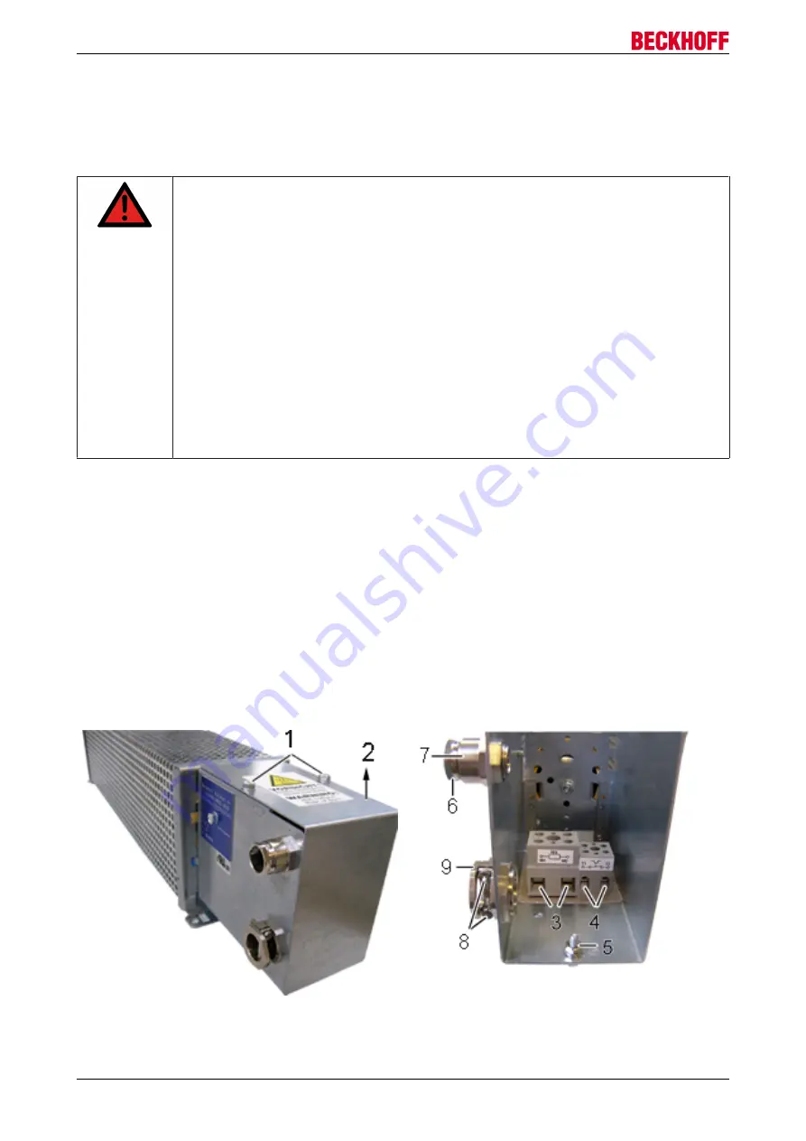
Remove the two screws (1) and remove the cover (2) in direction of the arrow. Connect an adequately
dimensioned cable (see chapter "Cables") to the connections (3) of the resistor and the earthing stud (5) and
take it out of the terminal box through the strain-relief assembly (9). Ensure adequate strain relief with the
two screws (8). Connect the other side of the cable to the DC link contact connector "X2" of the AX5000. The
connector is supplied with the AX5000. Connect the earthing cable to the earthing conductor of the control
cabinet.

Connect an adequately dimensioned cable to the potential-free N/C contact (4) of the temperature switch
and take it out of the terminal box through the strain-relief assembly (7) (see chapter "Temperature switch").
Ensure adequate strain relief with the nut (6).

Install the cover (2) in reverse order.

Summary of Contents for AX2090-BW5 Series

Page 1: ...Documentation External brake resistor AX2090 BW5x Accessories for Beckhoff servo drive AX5000 1 3 2018 03 14 Version Date...

Page 2: ......

Page 3: ...tion of symbols 8 2 3 Safety rules 9 3 Product identification 10 4 Mechanical installation 11 4 1 Mounting positions and distances 11 5 Electrical installation 12 5 1 Important notes 12 5 2 Connection...

Page 4: ...Table of content External brake resistor AX2090 BW5x 4 Version 1 3...

Page 5: ...f the data diagrams and descriptions in this documentation Trademarks Beckhoff TwinCAT EtherCAT Safety over EtherCAT TwinSAFE XFC and XTS are registered trademarks of and licensed by Beckhoff Automati...

Page 6: ...rs and the machine are brought into a safe state in the event of a fault in the drive system The external brake resistors of the AX2090 BW5x xxxx series are able to convert the dynamic energy generate...

Page 7: ...the liability of Beckhoff Automation GmbH Co KG Failure to comply with this documentation Improper use Untrained personnel Use of unauthorized spare parts 2 1 Staff qualification Only technical perso...

Page 8: ...sregarding the safety notice may lead to serious injuries CAUTION Personal injuries This is a dangerous situation Disregarding the safety notice may lead to minor injuries Symbols that warn of damage...

Page 9: ...s connected from the mains supply After disconnecting the servo drive wait at AX5101 AX5125 and AX520x 5 minutes at AX5140 AX5160 AX5172 15 minutes at AX5190 AX5191 30 minutes and at AX5192 AX5193 45...

Page 10: ...scope of supply always includes Brake resistor of the appropriate performance class Technical documentation this documentation Packaging Name plate Figure Pos No Description 1 Type power at 40 C 2 Res...

Page 11: ...0 xxxx AX2090 BW51 1000 AX2090 BW51 3000 and AX2090 BW51 6000 AX2090 BW52 3000 and AX2090 BW52 6000 AX2090 BW53 3000 and AX2090 BW53 6000 AX2090 BW54 3000 and AX2090 BW54 6000 For all mounting positio...

Page 12: ...it 5 minutes for the AX5101 AX5125 and AX520x 15 minutes for the AX5140 AX5160 AX5172 30 minutes for the AX5190 AX5191 45 minutes for the AX5192 AX5193 after disconnecting and measure the voltage at t...

Page 13: ...ake resistors can reach temperatures of almost 200 C Therefore ensure adequate thermostability of the cables Cables with inadequate thermostability can cause a cable fire Attention EMC safety Use only...

Page 14: ...X2090 BW52 3000 85 2 AX2090 BW52 6000 85 2 AX2090 BW53 3000 85 2 AX2090 BW53 6000 85 2 AX2090 BW54 3000 85 2 AX2090 BW54 6000 85 2 5 5 Short term capacity Brake resistors are usually not operated cont...

Page 15: ...Normal operating range max 130 Permitted operating range max 160 Inadmissible operating range more than 160 This operating range is recommended for maximum service life and error free opera tion This...

Page 16: ...0 BW51 3000 3000 23 4 490 355 255 380 270 8 AX5118 AX5140 AX2090 BW51 6000 6000 23 2 490 455 255 380 370 12 AX5118 AX5140 AX2090 BW52 2000 3000 13 2 490 355 255 380 270 8 AX5160 AX5172 AX2090 BW52 600...

Page 17: ...Technical data External brake resistor AX2090 BW5x 17 Version 1 3 Technical drawings...

Page 18: ...for Beckhoff components there Beckhoff Headquarters Beckhoff Automation GmbH Co KG Huelshorstweg 20 33415 Verl Germany Phone 49 0 5246 963 0 Fax 49 0 5246 963 198 e mail info beckhoff com Beckhoff Su...

Reviews: