background image

For your safety

AL225x Connector-Box

10

Version: 1.9

3.3

Special safety instructions for the connector box

The safety instructions are designed to avert danger and must be followed during installation,
commissioning, production, troubleshooting, maintenance and trial or test assemblies. The connector boxes
of the AL225x series are not designed for stand-alone operation and are always installed in a machine or
system. After installation, the documentation the documentation and the safety instructions provided by the
machine manufacturer must be read and applied.

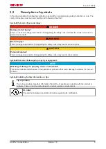
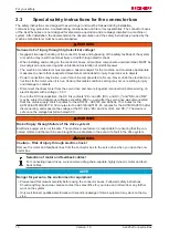
 WARNING

Serious risk of injury through high electrical voltage!

• Negligent, improper handling of the connector boxes and bypassing of the safety facilities of the system

or machine may result in personal injury or death through electric shock.

• When installing and working on the connector boxes, all machine components and assemblies MUST be

de-energized and secured against unintentional restoration of electrical power.

• The machine manufacturer must prepare a hazard analysis for the machine, and must take appropriate

measures to ensure that unexpected movements cannot lead to injury to persons or to objects.

• Power connections may be live, even if machine components don't move. Never undo the electrical con-

nections to the motor when it is live. Under unfavorable conditions arcing may occur, resulting in injury
and damage to contacts.

• Disconnect the linear motor from the servo drive and secure it against reconnection before working on

electrical parts with a voltage > 50 V.

• Due to the DC link capacitors, the DC link contacts "ZK+ and ZK- (DC+ and DC-)" and "RB+ and RB-"

may be subject to dangerous voltages exceeding 890V

DC

, even after the servo drive was disconnected

from the mains supply. Wait 5 minutes for the AX5101 - AX5125 and AX520x; 15 minutes for the
AX5140/AX5160/AX5172; 30 minutes for the AX5190/AX5191; 45 minutes for the AX5192/AX5193 after
disconnecting, and measure the voltage at the DC links "ZK+ and ZK- (DC+ and DC-)". The device is
safe once the voltage has fallen below 50 V.

 WARNING

Risk of injury through failure of the drive system!

Electronic equipment is not fail-safe. The machine manufacturer is responsible for ensuring that the con-
nected motors and the machine are brought into a safe state in the event of a fault in the drive system.

 WARNING

Caution – Risk of injury through electric shock!

Remove the motor and feedback lines from the connector box to the servo drive when you open the con-
nector box.

Selection of motor and feedback cables!

For connecting linear drives, we recommend drag chain-capable, highly dynamic motor and feed-
back cables.

NOTE

Danger for persons, the environment or equipment

• Please read this manual carefully before using the connector boxes. Follow all safety instructions.

Should anything be unclear, please contact the sales office for your area and refrain from any further
work on the system.

• Only well trained, qualified electricians with sound knowledge of drive equipment may work on the de-

vice.

Summary of Contents for AL-2255-0001

Page 1: ...Operating instructions AL225x Connector Box Accessory for servo drives of the series AX5000 and AX2000 1 9 2019 05 15 Version Date...

Page 2: ......

Page 3: ...11 4 2 Name plate 11 4 3 Type key 11 5 Technical description 12 5 1 Configuration of the connector boxes 12 5 2 Connection technology AL225x 0001 at AX5000 13 5 3 Connection technology AL225x 0000 at...

Page 4: ...Contents AL225x Connector Box 4 Version 1 9...

Page 5: ...ta diagrams and descriptions in this documentation Trademarks Beckhoff TwinCAT EtherCAT Safety over EtherCAT TwinSAFE XFC and XTS are registered trademarks of and licensed by Beckhoff Automation GmbH...

Page 6: ...technology AL225x 0000 at AX2000 5 3 1 6 Chapter update Name plate 4 2 Type key 4 3 Dimensional drawing Connector Box 8 1 8 3 1 5 Chapter update 1 0 Foreword 3 0 Safety 1 4 Chapter update 5 2 5 3 1 3...

Page 7: ...2 Guidelines and Standards In addition to the safety instructions mentioned in this manual the general statutory and other rules and regulations for the prevention of accidents e g personal protective...

Page 8: ...the liability of Beckhoff Automation GmbH Co KG Failure to comply with this documentation Untrained personnel Use of unauthorized spare parts 3 1 Staff qualification Only technical personnel with kno...

Page 9: ...egarding the safety notice may lead to serious injuries CAUTION Personal injuries This is a dangerous situation Disregarding the safety notice may lead to minor injuries Symbols that warn of damage to...

Page 10: ...s Disconnect the linear motor from the servo drive and secure it against reconnection before working on electrical parts with a voltage 50 V Due to the DC link capacitors the DC link contacts ZK and Z...

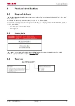
Page 11: ...ing seal Before commissioning the products check the delivery for completeness Should delivered components be damaged notify the logistics company and Beckhoff Automation GmbH Co KG immediately Connec...

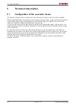
Page 12: ...each connector box has ports for Beckhoff motor and feedback cables on the input side The output side features screw connections through which non assembled motor and feedback system cables can be in...

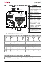
Page 13: ...blue green yellow blue orange X2 4 5 VDC brown red brown brown red X2 5 DATA white blue grey pink X2 6 US 9 V X2 7 REF Z X2 8 Clock X2 9 SIN yellow blue orange yellow yellow X2 10 GND sense grey X2 1...

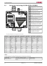
Page 14: ...llow blue orange yellow yellow X2 4 5 VDC brown red brown brown red X2 5 DATA Z white blue grey pink X2 6 n c X2 7 PTC X2 8 Clock X2 9 COS blue green yellow blue orange X2 10 GND sense grey X2 11 SIN...

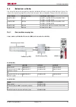
Page 15: ...03 AL2830 0001 and AL2830 1000 AL3803 AL3818 0000 AL2255 0001 AX5xxx AL2830 1001 0000 and AL2845 1000 0000 AL2256 0001 AX5xxx AL2845 1001 0000 5 4 1 Connection examples Linear motors with Beckhoff enc...

Page 16: ...or encoder with zero pulse ZK4520 0020 Linear motors with Beckhoff encoder MES without connector box Cable AX2000 AX2500 AX5000 Motor cable ZK4000 2111 ZK4000 2711 ZK4500 0023 Thermal protection conta...

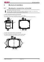
Page 17: ...e The connector box must therefore be mounted on the moving part of the linear axis Connector boxes AL2250 0000 and AL2250 0001 The connector boxes are mounted with 2 screws e g M4 DIN13 Remove the co...

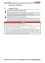
Page 18: ...rew the nut onto socket B Fit a PE connection to the shielded cable Wire the signal wires to the X2 connection as per the table DANGER Serious risk of injury through high electrical voltage The connec...

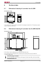
Page 19: ...M4 flat head screws DIN 7984 8 2 Dimensional drawing of connector box AL2255 AL2256 All dimensions in mm 2 The holes on the mounting lugs are provided for M5 flat head screws 3 The holes with M4 x 20...

Page 20: ...ckhoff components there Beckhoff Headquarters Beckhoff Automation GmbH Co KG Huelshorstweg 20 33415 Verl Germany Phone 49 0 5246 963 0 Fax 49 0 5246 963 198 e mail info beckhoff com Beckhoff Support S...

Reviews: