background image

Hazardous moving parts of the drive must be installed at a height of over 2.5 m above floor level or any
other surface from which the drive can be accessed.

To ensure safe operation of the system after commissioning, the limit positions must be correctly set/
programmed in.

Drives with a H05VV-F connecting cable may only be used indoors.

Drives with a H05RR-F, S05RN-F or 05RN-F connecting cable may be used both indoors and outdoors.

To connect the drive to the driven part, solely mechanical accessory components made by the drive
manufacturer from the current product catalogue may be used. The components must be installed in
accordance with the manufacturer's instructions.

If the drive is used for shading solutions in a specially marked area (e.g., escape routes, hazard zones,
safety areas), compliance with all applicable regulations and standards must be ensured.

Once the drive has been installed, the fitter must mark the used tubular drive in the “Technical data”
chapter and make a note of the installation position.

Caution

Safety instructions for avoiding serious injuries.

When electrical or electronic equipment and units are operated, certain components,
e.g., the power supply unit, are live. Physical injuries or damage to property can result in
the event of unauthorised interventions or failure to heed warnings.

Be careful when touching the tubular drive, as it heats up during operation for technical
reasons.

Before installation, shut down all lines and control devices that are not essential for op-
eration.

Crushing or shearing points must be avoided or protected.

When installing the drive, all-pole disconnection from the mains with a contact gap of at
least 3 mm per pole must be provided (EN 60335).

If the mains connecting cable is damaged, it may only be replaced by the manufacturer.
If the drive has a plug-in connecting cable, it must be replaced with the same type of
mains connecting cable, which is available from the drive manufacturer.

Attention

Safety instructions for avoiding property damage.

Ensure that there is adequate clearance between moving parts and adjacent objects.

The drive must not be carried by the mains connecting cable.

All latching connections and fastening screws on the brackets must be checked to en-

sure that they are secure.

Ensure that nothing rubs against the tubular drive, such as shading solution attach-

ments, screws, etc.

The drive must be fitted horizontally.

5 - en

Summary of Contents for P5-20-C18 PLUS

Page 1: ...ated radio transceiver for ZIP systems Important information for Fitters Electricians Users Please forward accordingly These instructions must be kept safe for future reference Becker Antriebe GmbH Friedrich Ebert Straße 2 4 35764 Sinn Germany www becker antriebe com 2010 301 285 0a 06 07 2022 ...

Page 2: ... of the tubular drive to factory settings 19 Commissioning with a Centronic transmitter 21 Programming the master transmitter 22 Checking that the running direction is correct 22 Intelligent installation management 23 Limit position status indicator 23 Setting the limit positions 23 Lower point to upper point 23 Lower point to upper stop 24 Deleting the limit positions 24 Intermediate positions I ...

Page 3: ...on are accommodated automatically when using stop systems Suitable for vertical sun protection Considerably reduced stop load and thus considerably reduced fabric load Activate deactivate the fabric untensioning function Left or right hand installation Several drives can be operated in parallel Automatic adjustment of direction of rotation Smooth operation of the system and the drive increases the...

Page 4: ... equipment during operation Ensure that there is adequate clearance at least 40 cm between moving parts and adjacent objects Caution Safety instructions for avoiding serious injuries Crushing or shearing points must be avoided or protected Instructions for installation and commissioning General information Observe the safety instructions in EN 60335 2 97 Please note that this list of safety instru...

Page 5: ...ronic equipment and units are operated certain components e g the power supply unit are live Physical injuries or damage to property can result in the event of unauthorised interventions or failure to heed warnings Be careful when touching the tubular drive as it heats up during operation for technical reasons Before installation shut down all lines and control devices that are not essential for o...

Page 6: ...jury and property damage The drive manufacturer does not accept liability for damages or injury arising from such actions Always observe the information in these instructions when operating or repairing the system The drive manufacturer does not ac cept liability for damage or injury resulting from improper usage Assembling and disassembling the plug in connecting cable Caution The power supply to...

Page 7: ...embly the power supply must be disconnected and secured Please give the enclosed connection information to the responsible electrical contractor Calculate the space required at the side M by measuring the drive head 1 and wall bracket 2 The clear dimension of the box X minus the space required at the side M and idler G gives the length L of the barrel L X M G The space required at the side M varie...

Page 8: ...on for round shafts we recommend screwing the drive adapter to the shaft see the table below Attention When drilling into the barrel never drill near the tubular drive Size of drive mm Drive adapter Torque max Nm Fastening screws 4 units dia 35 dia 45 All Up to 50 Self tapping screw dia 4 8 x 9 5 mm We also recommend screwing the idler to the barrel Attention Do not hammer the tubular drive into t...

Page 9: ...e of the CentronicPlus radio control system is not available in this combination When using the Centronic transmitter with CentronicPlus receiver the range perform ance may be reduced under certain circumstances A Centronic transmitter cannot process feedback from the CentronicPlus re ceiver The full performance of CentronicPlus is only achieved in combination with CentronicPlus transmitters recei...

Page 10: ...ired receiver and channel allocation Setting mode Commissioning and administration of selected receivers Attention The tubular drives are designed for short time operation An inbuilt thermal protection switch prevents overheating of the tubular drive During commissioning long drop dis tance or long running time the thermoswitch may trigger The drive will switch off After a short cooling down perio...

Page 11: ...tory settings Readying the tubular drive for programming by switching on the power Switch on the power The tubular drive confirms The tubular drive is ready to program for 15 minutes If several tubular drives are to be connected in parallel you can deactivate the program ming mode on one tubular drive by switching the radio switch to the outside position after turning the power on Readying the tub...

Page 12: ...white Centronic PLUS sensor selected Lights up purple Centronic PLUS transmitter selected Lights up red No receiver located Select the desired channel by pressing the function key on the multi channel hand held transmitter or Press the STOP button to change the assignment status of the selected receiver If the receiver is not yet part of the installation it will be added and assigned to the se lec...

Page 13: ...ver you can press the button to toggle between the available receivers until the required receiver confirms Pressing the button for 3 seconds confirms the receiver with the best connection quality The transmitter displays the current assignment status of the receiver via the LED ring Assignment status Lights up yellow The receiver is not yet part of the installation or is in the as delivered condi...

Page 14: ...on will now have changed Check the running direction again Changing the direction of rotation with a CentronicPLUS transmitter Select the required receiver as described in the chapter Selection of the receiver for the setting mode 13 Press the or button The shading solution runs in the desired direction The running direction is OK Now change back to normal mode as described in the previous step If...

Page 15: ...by opening or closing again There are several ways to set the limit positions Lower point to upper point Lower point to upper stop Auto install The limit position becomes fixed after the tubular drive has turned off automatically in the desired position three times Lower point to upper point There is no shading solution length adjustment with this limit position setting Select the required receive...

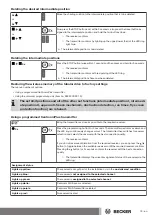
Page 16: ... goes out Changing the set limit positions 1 Shortening the range of travel the desired limit position is located inside the current range of travel Select the required receiver as described in the chapter Selection of the receiver for the setting mode 13 Open close to the desired new limit position or First press and hold the programming button then within 3 seconds also press and hold the button...

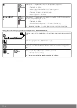
Page 17: ...ld the button for the extend limit position or the button for the retract limit pos ition Hold the two buttons down The tubular drive confirms The transmitter confirms by lighting up the upper lower third of the LED ring The new limit position is now saved 3s Then press the programming button for 3 seconds to change to normal mode The LED ring goes out Deleting the limit positions Attention When b...

Page 18: ...ermediate posi tion Both limit positions must be set before an intermediate position is set Setting modifying the desired intermediate position Open close the shading solution to the desired intermediate position or Press the STOP button and within 3 seconds also press the desired travel button and hold the two buttons down The receiver confirms The transmitter confirms by lighting up the upper lo...

Page 19: ...nti freeze mechanism obstruction detection run times fly screen protection function are retained Using a programmed CentronicPlus transmitter Bring the transmitter as close as possible to the required receiver 3s Press the programming button for 3 seconds The transmitter performs a search and the LED ring continuously changes colour The transmitter then switches to receiver selection and selects t...

Page 20: ...tter confirms with a red rotation of the LED ring The wireless memory of the tubular drive is now restored to factory settings Using the universal programming unit item no 4935 000 001 0 Connect the wires of the tubular drive to those of the same colour in the programming unit Connect the programming unit to the mains supply Now press and hold the button Tubular drive with electronic limit switchi...

Page 21: ... for operation again The drive does not achieve its full duty cycle until it has cooled to ambient temperature Avoid a situation where the thermal protection switch cuts in repeatedly Connecting the tubular drive N 1 2 1 2 4 3 4 230V AC 50 Hz L1 PE Connect the tubular drive to the power supply 1 blue 3 black 2 brown 4 green yellow Switch on the power The tubular drive confirms Readying the tubular...

Page 22: ...ming button for 10 seconds Checking that the running direction is correct The direction of rotation can only be changed if no limit position has been set There are several ways to change the direction of rotation Changing direction of rotation via the direction switch Changing direction of rotation via master transmitter Changing direction of rotation via the direction switch Press the or button T...

Page 23: ...hutter direction must be correct When setting the limit positions the tubular drive runs in dead man mode and limit position status indicator The lower limit position must always be set first If the tubu lar drive switches off prematurely while opening or closing due to an obstruction the ob struction can be cleared by opening or closing the screen and removing the obstruction The desired limit po...

Page 24: ...for 10 seconds The tubular drive acknowledges The limit position is now deleted Deleting both limit positions Any additional functions that may have been set are deleted at the same time or are reset to the factory default settings Open close the shading solution to a point between the limit positions Press the programming button and within the next 3 seconds press the STOP button at the same time...

Page 25: ...ges 3s Now press the programming button of a new transmitter which has not yet been pro grammed in the tubular drive for 3 seconds Doing so activates the programming mode of the tubular drive for a new transmitter for 3 minutes The tubular drive acknowledges 3s Now press the programming button of the new transmitter you wish to program again for 3 seconds The tubular drive acknowledges The new tra...

Page 26: ...ching back on the power execute a drive or stop command using the transmitter for the given tubular drives or switch the radio switch from inside to outside If the radio switch is already in this position switch it to the inside and back to the outside position N 1 2 1 2 4 3 4 230V AC 50 Hz L1 PE Switch off the tubular drive power for 5 seconds then switch it back on The tubular drive is ready to ...

Page 27: ...stacle detection for ZIP applications with heavy end strip Caution Obstacle detection is only active in conjunction with the drive adapter for obstacle detec tion In addition please note that the drive must be pushed in to the shaft as far as the band of the thrust ring Use of the drive s obstacle detection system as personal protection is not permitted It has been designed exclusively to protect ...

Page 28: ...r limit position 3s Then press the programming button again and also the STOP and buttons for ap prox 3 seconds The tubular drive confirms The fabric untensioning function is now activated deactivated Restoring the factory settings of the tubular drive The factory settings can only be restored via the universal programming unit Item no 4935 000 001 0 Connect the wires of the tubular drive to those...

Page 29: ... Operation proceeds in this sequence Travel Stop Travel in the opposite direction Stop 1 second Moves in maintained operation 1 second Moves in dead man mode Double tap 1 second Moves to the intermediate position in altern ation if both are programmed Disposal The crossed out bin symbol on the product indicates that the device is subject to mandatory disposal separate from household waste This pro...

Page 30: ... PLUS Type C PSOF Z1 PLUS Rated torque Nm 8 12 20 30 40 Output speed rpm 17 17 17 17 17 Limit switch range 64 revolutions Supply voltage 230 V AC 50 Hz Connected load W 100 110 160 205 260 Rated current consumption A 0 45 0 50 0 75 0 90 1 15 Operating mode S2 4 min Degree of protection IP 44 Min tube inside diameter mm 47 Frequency 868 3 MHz Emission sound pressure level dB A 70 Error messages 10x...

Page 31: ...ly UP until you reach the upper limit position The LED ring lights up red when the receiver for the setting mode is selected Reduce distance from receiver Check electr connection of the receiver Put the receiver into programming mode Add the transmitter to the installation The required setting cannot be changed Make sure that the CentronicPlus transmitter is in setting mode Tubular drive overruns ...

Page 32: ...on and reverses How ever it does not double check again whether the obstruction is still there The installation is not yet complete Travel to the limit position Stop three times Sample wiring diagram N L PE Electronics Black Brown Blue Green yellow 32 en ...

Page 33: ...Declaration of conformity 33 en ...

Page 34: ...34 ...

Page 35: ...35 ...

Page 36: ......

Reviews: