


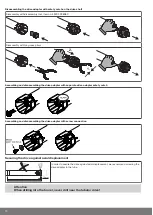


Assemble the tubular drive with the relevant ring (1) and drive adapter (2). If the ring
has several grooves, select the groove which is a perfect fit and push the ring (1) onto
the thrust ring.
Insert the tubular drive with the pre-assembled ring (1) and drive adapter (2) into the
tube to achieve a form fit. Ensure that the ring and drive adapter are secure in the
tube.
Mount the assembled unit comprising barrel, tubular drive and idler on the box and secure the drive with a split or spring pin ac-
cording to the type of wall bracket fixing.
The drive can be operated either with the switch (Item no. 4901 001 158 0) or the op-
erator control provided.
Connect the pigtail wires of the tubular drive to those of the same colour in the switch
or operator control and switch on the power supply. Check the direction of travel. If
the direction of travel of the shading solution does not correspond to the operator
control, swap the black and brown pigtail wires of the tubular drive.
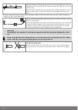
Attention
The switch is not suitable for continuous operation and has only been designed for start-
up!
When using springs/anti-lifting devices, we recommend you use at least three; for longer
tubes, use three springs/anti-lifting devices per metre of barrel.
Lay the connecting cable
Lay the connecting cable up to the tubular drive, and fix The connecting cable and
any antennae must not project into the winding chamber. Cover any sharp edges.
12


