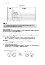
DMX data cable
Use a Tronios DMX data cable or equivalent cable which meets the specifications for EIA RS-485
applications. Standard microphone cables cannot transmit DMX data reliably over long distances.
3.3 3-Pin to 5-Pin conversion chart
Note! If you use a controller with a 5 pin DMX output connector you will need to use a 5pin to 3 pin
adapter.
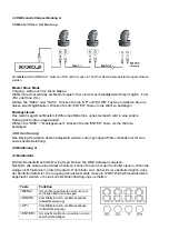
3.4 Setting up a DMX serial data link
At first link the first light and DMX control through XLR-connection signal cable, then devalued the light in
series ,as the follow
3.5 Master/Slave fixture linking
1.Connect the (male) 3 pin connector side of the DMX cable to the output (female)3pin connector of the
first fixture.
2.Connect the end of the cable coming from the first fixture which will have a (female)3 pin
connector to the input connector of the next fixture consisting of a (male) 3 pin connector. Then proceed
to connect from the output as stated above to the input of the following fixture and so on.
3.6 Orientation
This fixture may be mounted in any position provided there is adequate room for ventilation.
4. Operating instructions
4.1 Navigating the control panel
Access control panel functions using fhe four panel buttons located directly underneath the LCD Display.
Button Function
<MENU>
Used to access the menu or
return to a previous menu option
<DOWN> Scrolls through menu options in
descending order
<UP>
Scrolls through menu options in
ascending order
<ENTER> Used to select and store the
current menu or option within a
menu


