BeagleBone DVI-D with
Audio Cape
System Reference Manual
Revision A1
Page 26 of 28
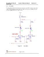
Q1 provides level shifting from the processor to drive the LED’s that are connected to
SYS_5V rail. FB8 provides noise immunity to the system by the LED’s which can be a
source of noise back into the system rail. Each LED is controlled by settings the
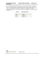
appropriate GPIO bit HI. At power up all LED’s are off. Table 3 is the GPIO User LED
assignments.
Table 3.
User LED Control
LED
GPIO
User 0
GPIO1_21
User 1
GPIO1_22


